Drawer type power control cabinet assembly with lighting device

A technology for power control cabinets and lighting devices, which is applied in the direction of pull-out switch cabinets, switchgear, electrical components, etc., and can solve problems such as complex operation, overturning, and influence on the stability of the cabinet

Active Publication Date: 2015-02-04
FUJIAN QINGYE ELECTRONICS CO LTD
View PDF8 Cites 3 Cited by
  • Summary
  • Abstract
  • Description
  • Claims
  • Application Information

AI Technical Summary

Problems solved by technology

However, after the drawer is pushed out, it is easy to affect the stability of the cabinet, and in serious cases, it may cause overturning and cause an accident
[0004] Howe

Method used


Image

  • Drawer type power control cabinet assembly with lighting device
  • Drawer type power control cabinet assembly with lighting device
  • Drawer type power control cabinet assembly with lighting device

Examples


Embodiment Construction

[0016] Underneath Figure 1-5 The present invention will be described in detail.

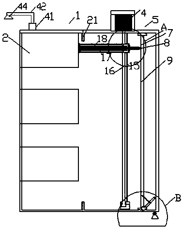
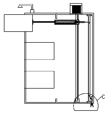
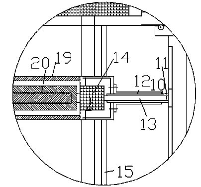
[0017] A drawer type power control cabinet assembly with lighting device, including a control cabinet part 1, a drawer push-out part 5 and a foot 25 fixed on the floor. The control cabinet part 1 and the drawer push-out part 5 are fixedly connected together to control The cabinet part 1 is provided with a plurality of power-controlled drawer boxes 2 placed up and down. The drawer push-out part 5 is used to push out the power-controlled drawer box 2 in the control cabinet part 1. The drawer push-out part 5 includes a supporting body and a lifting drive. Part, push drive part and lock drive part. The lift drive part includes a lift motor 4, a lift drive screw 16 and a guide rod 15. The lift motor 4 is connected to the upper end of the lift drive screw 16 for driving the lift drive screw 16 to rotate, The lower end of the lifting drive screw 16 is rotatably connected to the supporting body through a ...


PUM


Abstract

The invention a drawer type power control cabinet assembly with a lighting device. The drawer type power control cabinet assembly comprises a control cabinet part (1), a drawer push-out part (5) and feet (25) fixed on the floor, wherein the control cabinet part (1) is fixedly connected with the drawer push-out part (5); a plurality of power control drawer boxes (2) placed up and down are arranged in the control cabinet part (1); the drawer push-out part (5) is used for pushing out the power control drawer boxes (2) in the control cabinet part (1); the drawer push-out part (5) comprises a supporting body, a lifting drive part, a push-out drive part and a locking drive part; the lifting drive part comprises a lifting motor (4), a lifting driving screw (16) and a guide rod (15); the lifting motor (4) is connected with the upper end of the lifting driving screw (16) and used for driving the lifting driving screw (16) to rotate.

Description

Technical field [0001] The invention relates to the field of power control cabinets, and more particularly to a drawer type power control cabinet assembly with a lighting device. Background technique [0002] The power control cabinet is a common component in the field of power switch control. The power control cabinet is used to install various switches, controllers and other power equipment for power control. In order to facilitate maintenance, the power control cabinet usually has drawers for pushing and pulling to maintain the power equipment inside. [0003] In order to facilitate the automatic push and pull of the drawer, a motor is often set to push and pull the drawer. However, after the drawer is pushed out, it is easy to affect the stability of the cabinet, and it may overturn and cause an accident in severe cases. [0004] However, the normalized fixation of the cabinet will have the following disadvantages: when the cabinet needs to be moved flexibly, the normalized fi...

Claims


Application Information

Patent Timeline
IPC IPC(8): H02B11/133H02B11/173
CPCH02B11/133H02B11/173
Inventor 李长娟
Owner FUJIAN QINGYE ELECTRONICS CO LTD
Why Eureka
Try Eureka