Winding device

A winding device and strapping technology, which is applied in the directions of transportation, packaging, tires, applications, etc., can solve the problems of not being able to bind the beginning and end of the winding

Active Publication Date: 2015-02-04
THE YOKOHAMA RUBBER CO LTD
View PDF8 Cites 2 Cited by
  • Summary
  • Abstract
  • Description
  • Claims
  • Application Information

AI Technical Summary

Problems solved by technology

Therefore, there is a possibility that the winding start end and the winding end portion of the steel wire cannot be tightly bundled without looseness.

Method used


Image

  • Winding device
  • Winding device
  • Winding device

Examples


Embodiment Construction

[0021] Follow the Figure 1 to Figure 7 One embodiment of the wrapping device embodying the present invention will be described.

[0022] Such as figure 2 and Figure 5 As shown, the traveler B is formed by winding the wires W in a multi-row and multi-stage manner, thereby forming a ring shape and a polygonal cross-section with a substantially quadrilateral equal cross-section.

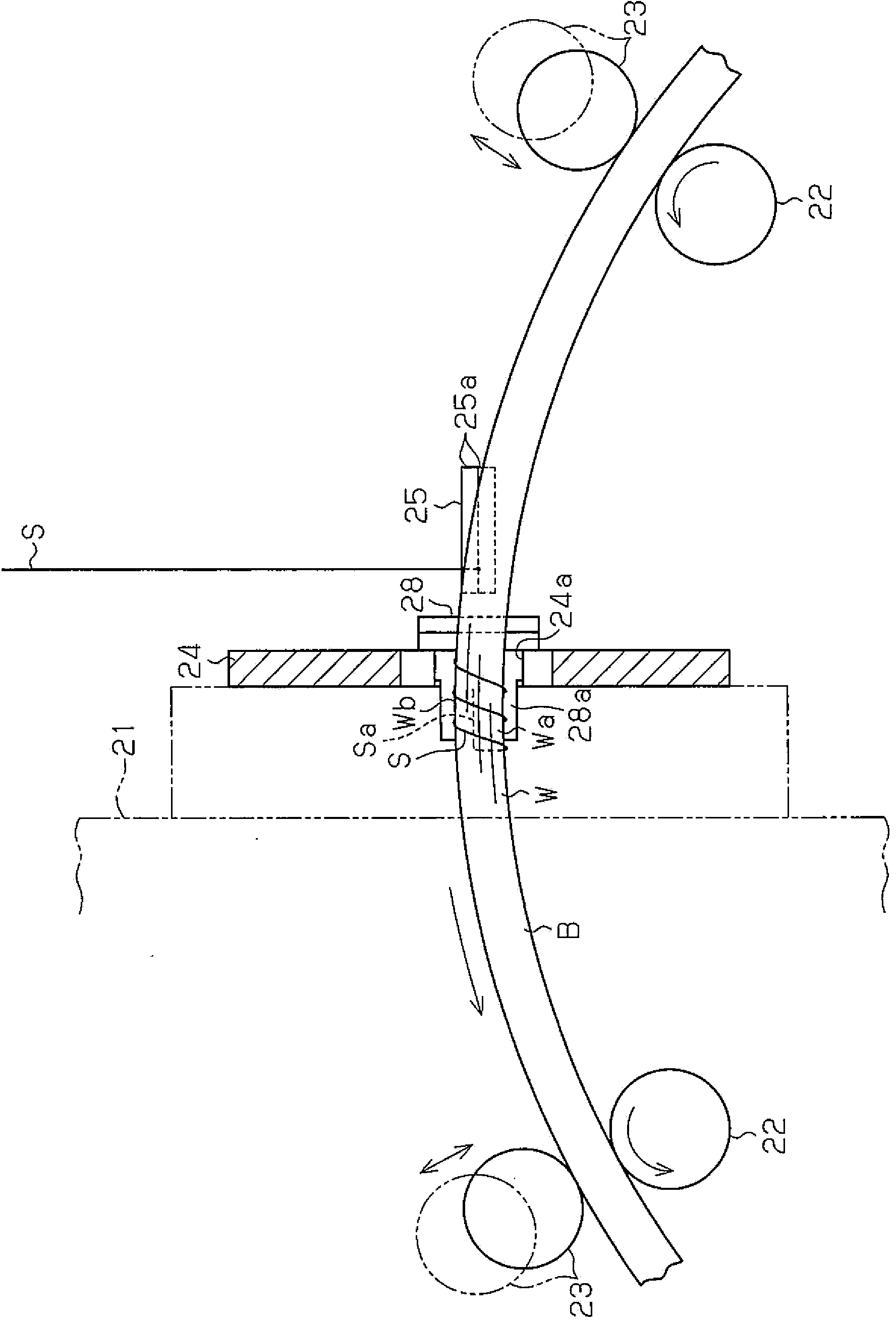
[0023] Such as figure 2 As shown, conveying rollers 22 , 23 for conveying the traveler B in the circumferential direction are supported on the device frame 21 . The traveler B moves along with the rotation of the conveying rollers 22 and 23 while being held between the conveying rollers 22 and 23 . figure 2 is transported in the counterclockwise direction.

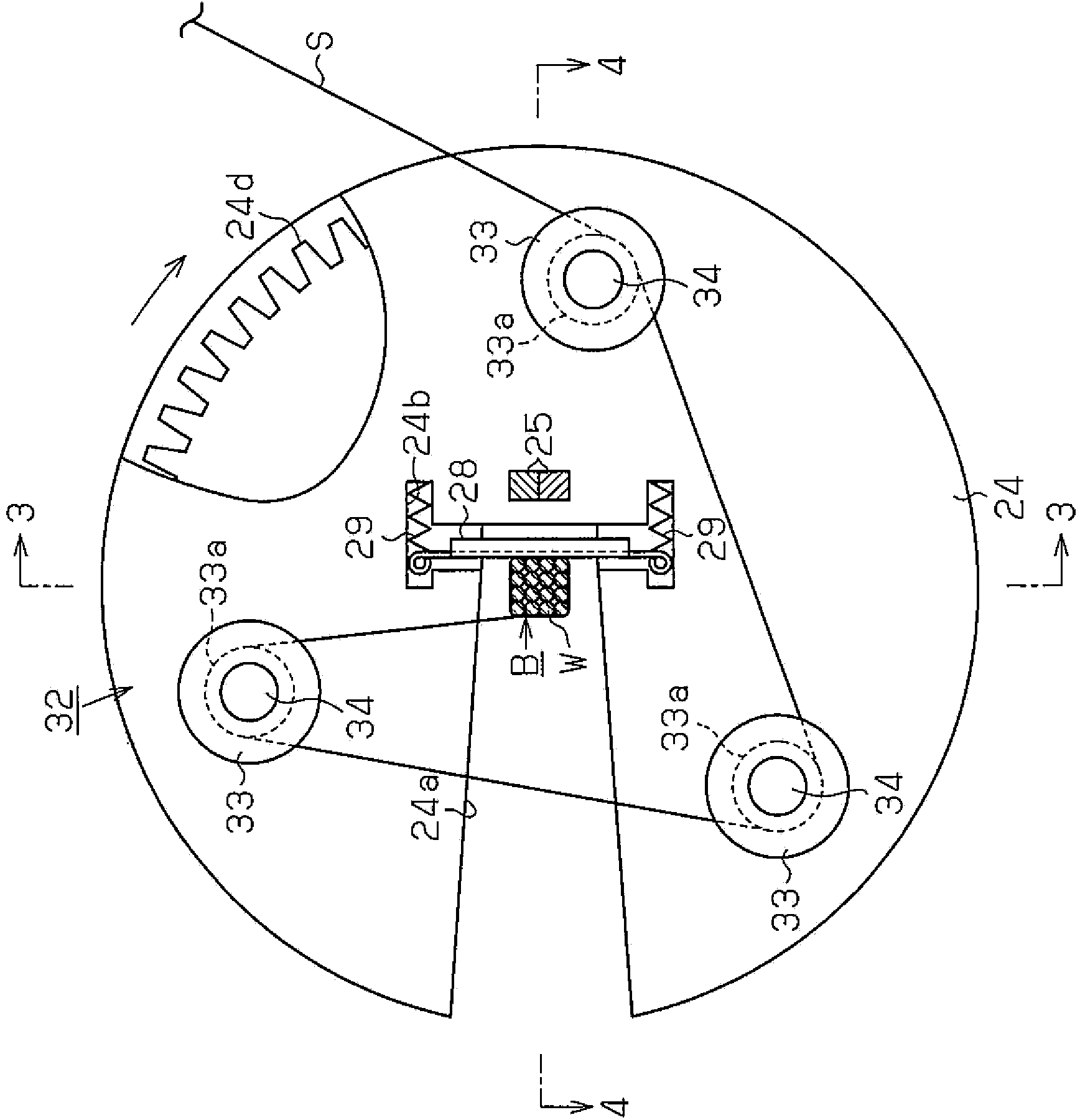
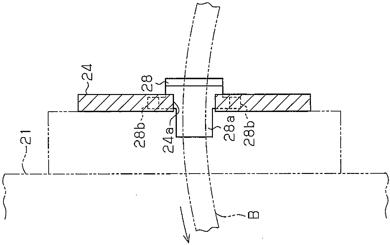
[0024] A disc-shaped rotating body 24 is supported on the device frame 21, and the rotating body 24 is used for winding the binding band S around the traveler B in a helical shape. The rotating body 24 can rotate in one direction around i...


PUM


Abstract

A winding device is provided with a rotating body (24) which, while a binding wire (S) is being held, rotates around an internal side and external side of an annular bead ring (B) being fed in the peripheral direction, thereby winding the binding wire (S) around the bead ring (B). A pressing member (28) which elastically presses the binding wire (S) onto the bead ring (B) is provided in the rotating body (24).

Description

technical field [0001] The present invention relates to a winding device for winding a binding tape around a traveler in order to bind a winding start end and a winding end portion of a steel wire when winding a steel wire to manufacture a traveler. Background technique [0002] Conventionally, as such a wrapping device, for example, a configuration disclosed in Patent Document 1 has been proposed. The winding device of this conventional configuration includes: a conveying roller for conveying an annular traveler formed by winding a wire in a circumferential direction; and a rotating body rotating while passing inside and outside of the traveler. Guide rollers for guiding the strapping are provided on the rotating body. A holding portion for releasably holding the start end of the strapping is provided on the side of the rotating body. The holding portion can approach and move away from a position near the rotation center of the rotating body. [0003] Then, the rotating ...

Claims


Application Information

Patent Timeline
Patent Type & Authority Applications(China)
IPC IPC(8): B21F37/00B29D30/48
CPCB29D30/50B29D30/48B29D2030/487B21F17/00B21F37/00B65H54/00
Inventor 野村诚明
Owner THE YOKOHAMA RUBBER CO LTD
Why Eureka
Try Eureka