Touch panel

A touch panel and substrate technology, used in instruments, electrical digital data processing, digital data processing components, etc., can solve problems such as the visual effect of touch panels, and achieve good visual effects and reduced reflectivity.

Inactive Publication Date: 2015-02-11
WINTEK CORP
View PDF6 Cites 9 Cited by
  • Summary
  • Abstract
  • Description
  • Claims
  • Application Information

AI Technical Summary

Problems solved by technology

However, since the reflectivity of the metal bridge is much higher than the reflectivity of the sensing pads made of transparent conductive material in the first sensing series and the second sensing series (the reflectivity of the metal bridge usually exceeds 50%), Affects the visual effect of the touch panel

Method used


Image

  • Touch panel
  • Touch panel
  • Touch panel

Examples


Embodiment Construction

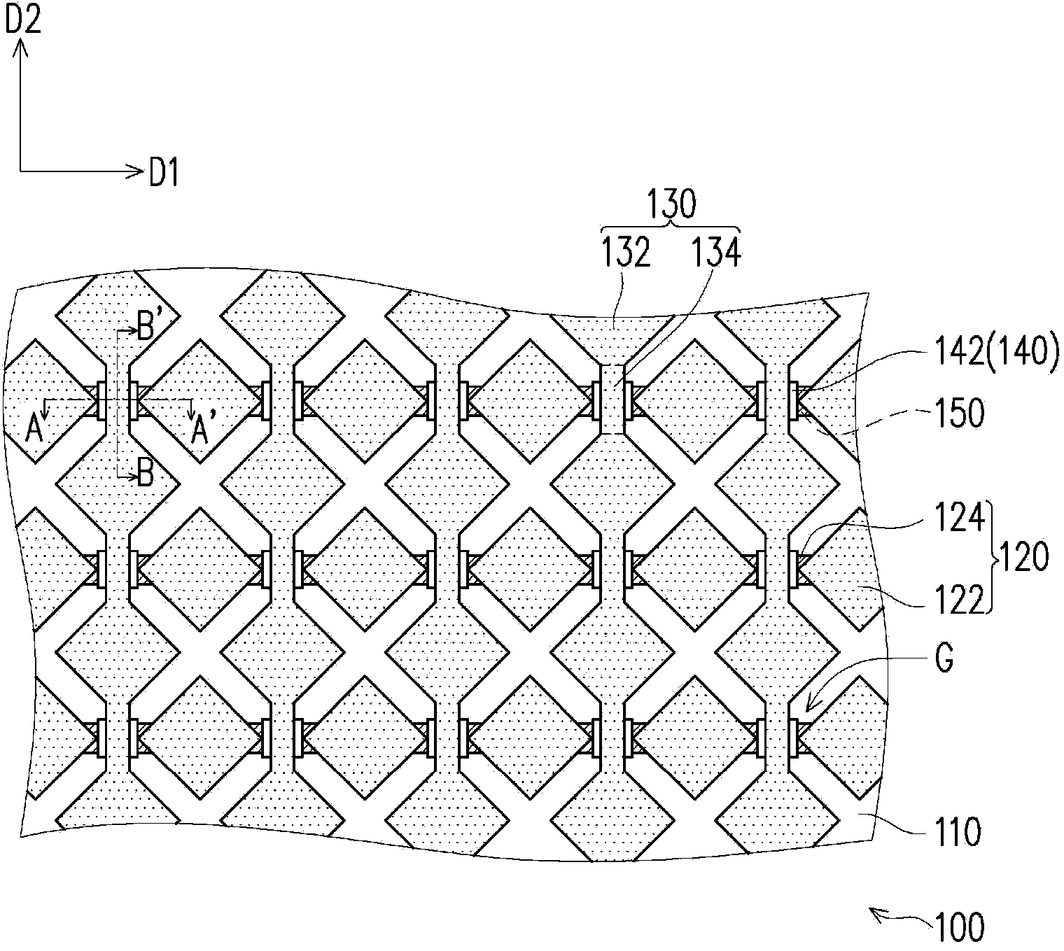
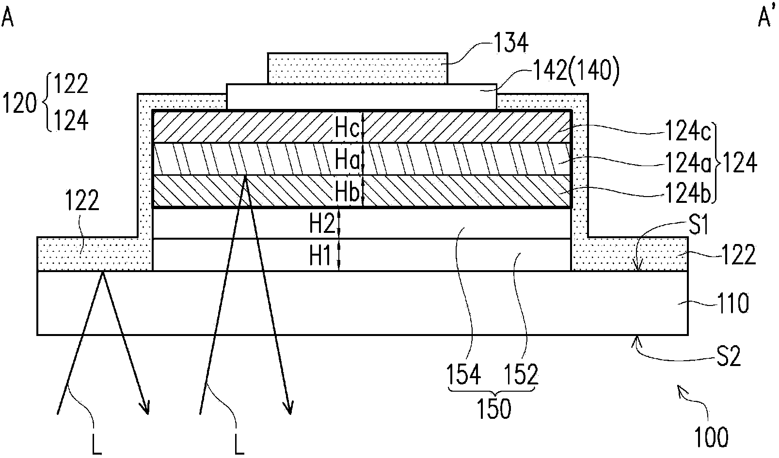
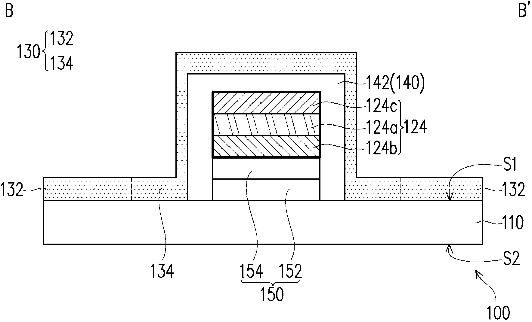
[0075] figure 1 It is a schematic partial top view of a touch panel according to the first embodiment of the present invention. Figure 2A and Figure 2B Respectively are figure 1 A schematic cross-sectional view of the middle section line A-A' and the section line B-B'. Reference figure 1 The touch panel 100 of this embodiment includes a substrate 110, a plurality of first sensing series 120, a plurality of second sensing series 130, and a plurality of optical matching stack structures 150.

[0076] The substrate 110 is used to carry the first sensing series 120, the second sensing series 130 and the optical matching stack structures 150. In this embodiment, the first sensing series 120, the second sensing series 130, and the optical matching stack structures 150 are, for example, disposed on the same surface S1 of the substrate 110. In addition, the material of the substrate 110 may be glass, sapphire glass, polyethylene terephthalate (PET), polymethylmethacrylate (PMMA), propy...


PUM


Abstract

A touch panel including a substrate, first sensing series and optical matching stacked structures is provided. Each first sensing series includes first sensing pads and bridge structures, and two adjacent first sensing pads are connected along the first direction through one of the bridge structure. Each optical matching stacked structure includes a first optical matching pattern and a second optical matching pattern disposed between the first optical matching pattern and the bridge structure, and the optical matching stacked structures are disposed on a surface of the bridge structures that faces to a user so as to reduce a reflectivity of light along a direction of view in areas where the bridge structures are located.

Description

Technical field [0001] The present invention relates to a touch panel, in particular to a touch panel capable of reducing the reflectivity of a bridge structure. Background technique [0002] With the rapid development and application of information technology, wireless mobile communications and information appliances, in order to achieve the purpose of convenient portability, lighter size and humanized operation, many information products have changed from traditional keyboard or mouse input devices to touch The touch panel is used as an input device. [0003] Taking a capacitive touch panel as an example, the existing capacitive touch panel includes a substrate, a plurality of first sensing series, a plurality of second sensing series, and a plurality of insulating patterns disposed on the substrate. The first sensing series and the second sensing series respectively have different extension directions and are interlaced with each other, and the first sensing series and the seco...

Claims


Application Information

Patent Timeline
Patent Type & Authority Applications(China)
IPC IPC(8): G06F3/042
CPCG06F1/1692G06F3/044G06F2203/04111G06F3/0443G06F3/0446
Inventor 吴易骏刘育承洪启元王圣成
Owner WINTEK CORP
Why Eureka
Try Eureka