Stirring device

A stirring device and a stirring plate technology, which is applied to mixers, dissolvers, mixers, etc. with rotating stirring devices, can solve problems such as long stirring time, reduced stirring effect, and increased resistance, and achieve increased stirring times, stirring The effect of improving the effect and increasing the contact area

Active Publication Date: 2016-06-29
广东逢春塑料包装有限公司
View PDF6 Cites 0 Cited by
  • Summary
  • Abstract
  • Description
  • Claims
  • Application Information

AI Technical Summary

Problems solved by technology

[0012] For example, the invention patent whose publication number is CN103100345A and the publication date is May 15, 2013, the agitator includes a first blade and a stirring shaft connected to the power output end of the halving device at one end, and the middle part of the first blade is fixedly connected with the other end of the stirring shaft. It also includes a second blade, a sleeve sleeved on the stirring shaft and sliding along the stirring shaft, and a motor fixed on the stirring shaft. The output end of the motor is connected with a telescopic rod for pushing and pulling the sleeve. One end of the second blade is connected to the first The ends of the blades are hinged, and an adjustment rod is hinged between the other end of the second blade and the sleeve; this patent can adjust the stirring position to make the liquid stir evenly, but its blades are short and cannot achieve better stirring. Secondly, the first The number of two blades is also large, the resistance of stirring is increased, and the cost is increased.
[0013] Publication CN104014268, a patent published on September 3, 2014, proposes a stirrer, including paddles connected to the motor through a rotating rod, the lower end of the rotating rod abuts against a support seat, and the support seat There is a base, the upper end of the base is provided with a support rod vertical to the horizontal plane, the upper outer wall of the support rod is provided with threads, and the nuts for adjusting the height of the support rod are set on the threads. When the agitator rotates, there is no looseness, no swing, and The paddle will not fall off and other advantages, but the design of the paddle is too simple, and the stirring force is lacking when stirring the liquid. This patent makes the stirring effect greatly reduced when pursuing light weight and convenient movement.
[0014] Therefore, aiming at the existing disclosed technology and practical application, this patent aims to propose a new technical solution to overcome the unsatisfactory stirring effect of the existing structural design, long stirring time and high energy consumption

Method used


Image

  • Stirring device
  • Stirring device

Examples


Embodiment 1

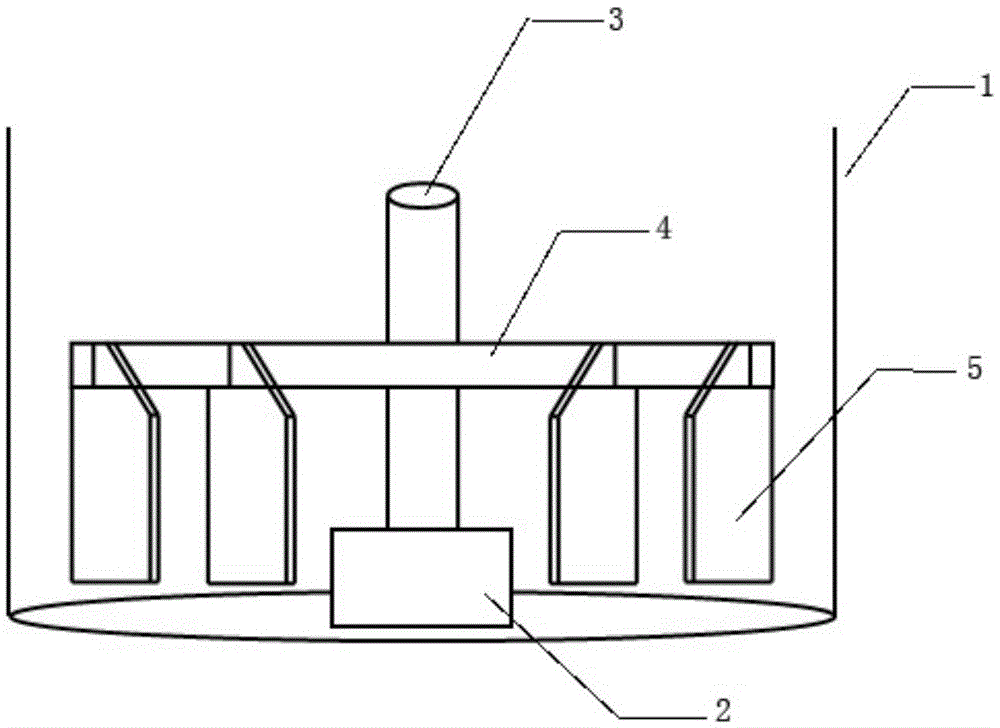
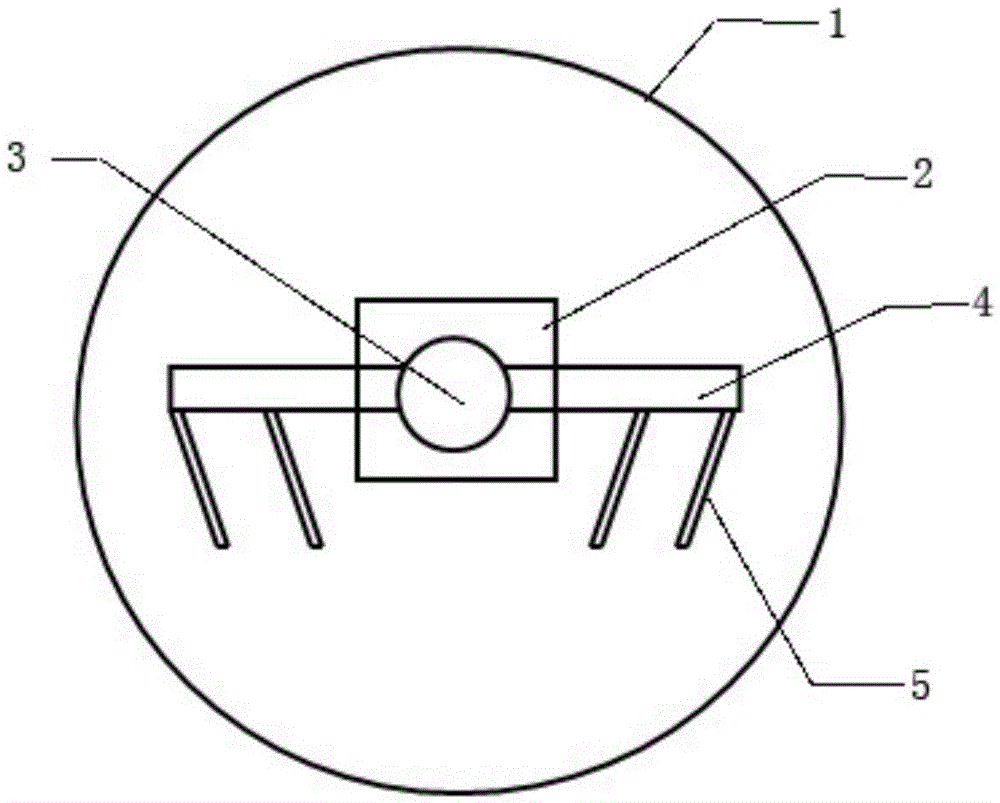
[0035] Such as figure 1 , 2 As shown, a stirring device includes a housing 1, a motor 2 installed at the center of the bottom of the housing 1, a stirring shaft 3 vertically installed above the motor 2, and a stirring beam 4 vertically fixed to the stirring shaft 3; it also includes a stirring plate 5 Two stirring plates 5 are respectively arranged on both sides of the stirring shaft 3, and the upper end of the stirring plate 5 is embedded and fixed on the cross section of the stirring beam 4 from the bottom surface of the stirring beam 4, and the plane of the stirring plate 5 is perpendicular to the bottom plane of the stirring beam 4; The stirring plate 5 is arranged in parallel, and the stirring plate 5 is arranged on the same side of the stirring beam 4; the distance between the bottom end of the stirring plate 5 and the bottom of the housing 1 is 5mm; the top of the stirring plate 5 is a right-angled trapezoidal steel plate , for embedding and fixing the part in the cros...

Embodiment 2

[0037] Referring to Embodiment 1, further, it includes a housing 1, a motor 2 installed at the center of the bottom of the housing 1, a stirring shaft 3 vertically installed above the motor 2, and a stirring beam 4 vertically fixed to the stirring shaft 3; a stirring plate 5 is also included ; At least two stirring plates 5 are arranged on both sides of the stirring shaft 3, and the stirring plates 5 on the same side of the stirring shaft are arranged in parallel.

Embodiment 3

[0039] Further, the stirring device of the present invention includes a housing 1, a motor 2 installed at the center of the bottom of the housing 1, a stirring shaft 3 vertically installed above the motor 2, and a stirring beam 4 vertically fixed to the stirring shaft 3; it also includes Stirring plate 5; the distance between the stirring plate 5 and the bottom of the housing 1 is 5 mm, so that the stirring plate 5 fully contacts the stirring material at the bottom of the housing 1 to achieve a better stirring effect.


PUM


Abstract

The invention discloses a stirring device which comprises a housing, a motor mounted in the bottom center of the housing, a stirring shaft vertically mounted above the motor, a stirring cross beam vertically fixed to the stirring shaft, and stirring plates, wherein the upper ends of the stirring plates are embedded and fixed to the lower part of the stirring cross beam from the bottom surface of the cross beam; the stirring plates are positioned on the same side of the stirring cross beam, and the included angles between the stirring plates and the two extending outer ends of the stirring cross beam are 95-175 degrees; the stirring plates are symmetrically arranged on the two sides of the stirring shaft. According to the stirring device, the stirring plates are arranged on the stirring cross beam, so that stirring parts are added; the stirring operation is performed through the stirring cross beam and the stirring plates; the two or more stirring plates are arranged on one side of the stirring shaft in parallel and rotationally tilt to the side wall of the housing or the stirring shaft along the horizontal plane; the area of contact between the stirring plates and stirring materials is enlarged, the materials are fully stirred, and the stirring effect is good.

Description

technical field [0001] The invention relates to a stirring device, which belongs to the field of industrial application. Background technique [0002] The stirring device generally consists of a motor, a rotating rod connected to the motor, and a stirring paddle arranged on the rotating rod. The function of the stirring device is to make the liquid and gas medium forced convection and uniform mixing. Most of the stirring devices currently used in industry The devices all have a single structure, and when stirring a liquid medium with a high density, the stirring effect is not good, and the service life of the parts of the stirring device is short. [0003] The purpose of stirring: liquid-liquid mixing, gas-liquid mixing and solid-liquid mixing. The influencing factors of stirring are as follows: [0004] 1) The type, size and rotational speed of the stirrer all have an influence on the distribution of stirring power between bulk flow and turbulent pulsation. [0005] 2) T...

Claims


Application Information

Patent Timeline
Patent Type & Authority Patents(China)
IPC IPC(8): B01F7/18
Inventor 钱国东
Owner 广东逢春塑料包装有限公司
Why Eureka
Try Eureka