An industrial liquid stirring device

A stirring device and liquid technology, which is applied to mixers, dissolvers, and mixers with rotating stirring devices, can solve the problems of long stirring time, increased resistance, and reduced stirring effect, so as to increase the number of stirring times and increase the Improvement of contact area and stirring effect

Active Publication Date: 2016-07-06
徐州元丰新材料科技有限公司
View PDF7 Cites 0 Cited by
  • Summary
  • Abstract
  • Description
  • Claims
  • Application Information

AI Technical Summary

Problems solved by technology

[0012] For example, the invention patent whose publication number is CN103100345A and the publication date is May 15, 2013, the agitator includes a first blade and a stirring shaft connected to the power output end of the halving device at one end, and the middle part of the first blade is fixedly connected with the other end of the stirring shaft. It also includes a second blade, a sleeve sleeved on the stirring shaft and sliding along the stirring shaft, and a motor fixed on the stirring shaft. The output end of the motor is connected with a telescopic rod for pushing and pulling the sleeve. One end of the second blade is connected to the first The ends of the blades are hinged, and an adjustment rod is hinged between the other end of the second blade and the sleeve; this patent can adjust the stirring position to make the liquid stir evenly, but its blades are short and cannot achieve better stirring. Secondly, the first The number of two blades is also large, the resistance of stirring is increased, and the cost is increased.
Publication CN104014268, a patent published on September 3, 2014, proposes a stirrer, including paddles connected to the motor through a rotating rod, the lower end of the rotating rod abuts against a support seat, and the support seat There is a base, the upper end of the base is provided with a support rod vertical to the horizontal plane, the upper outer wall of the support rod is provided with threads, and the nuts for adjusting the height of the support rod are set on the threads. When the agitator rotates, there is no looseness, no swing, and The paddle will not fall off and other advantages, but the design of the paddle is too simple, and the stirring force is lacking when stirring the liquid. This patent makes the stirring effect greatly reduced when pursuing light weight and convenient movement.
[0013] Therefore, aiming at the existing disclosed technology and practical application, this patent aims to propose a new technical solution to overcome the unsatisfactory stirring effect of the existing structural design, long stirring time and high energy consumption

Method used


Image

  • An industrial liquid stirring device
  • An industrial liquid stirring device

Examples


Embodiment 1

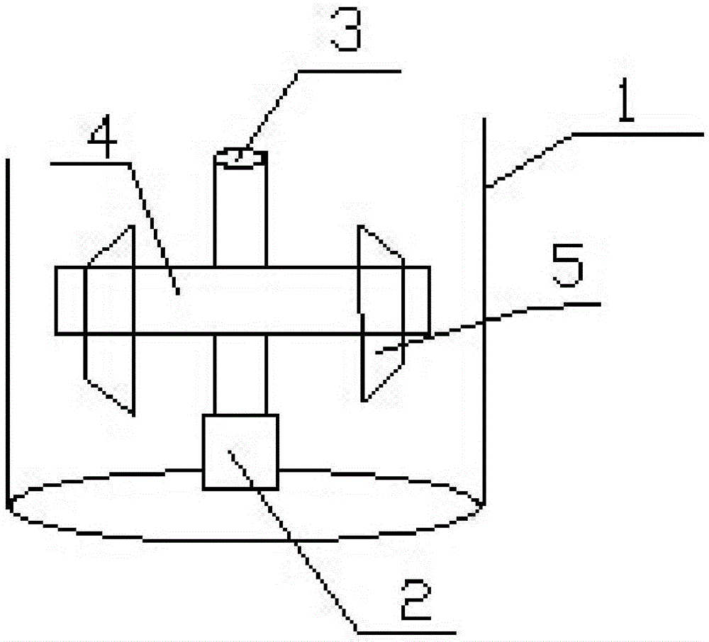
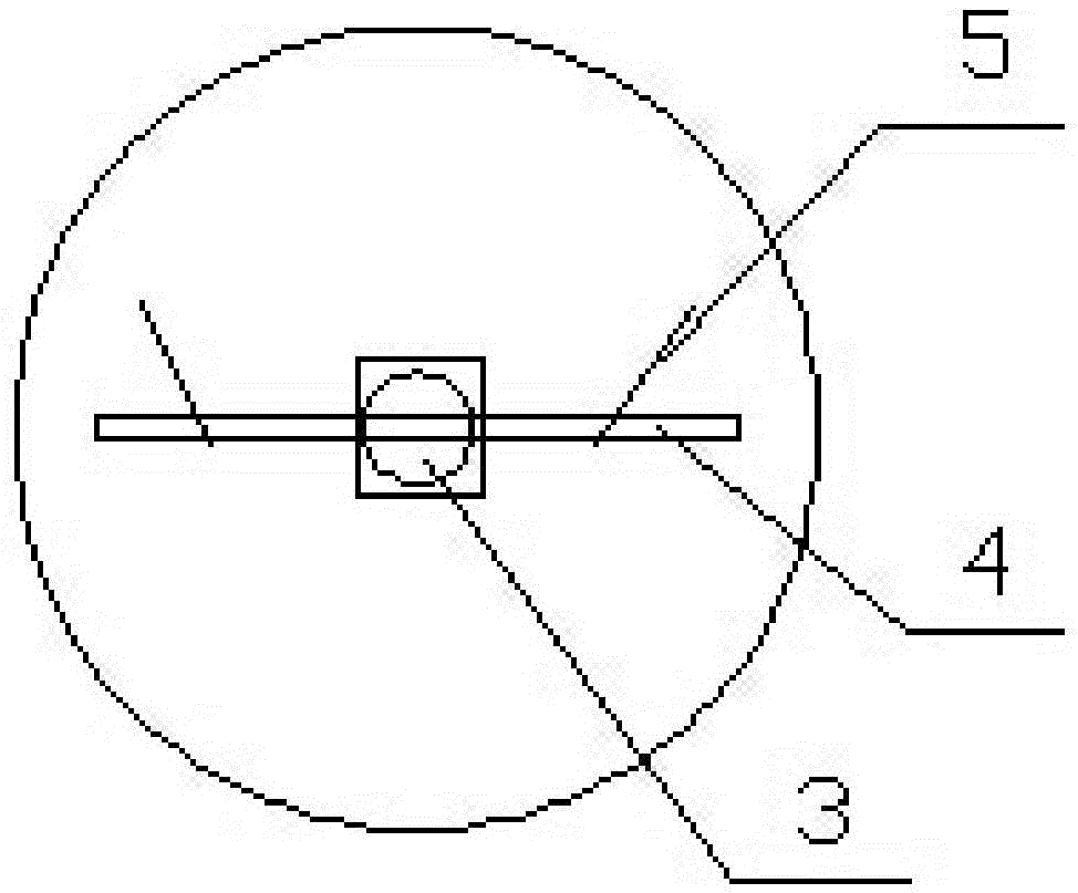
[0034] Such as figure 1 , 2 As shown, the industrial liquid stirring device includes a housing 1, a motor 2 installed at the center of the bottom of the housing 1, a stirring shaft 3 vertically installed above the motor 2, and a stirring beam 4 vertically fixed to the stirring shaft 3; it also includes a stirring plate 5 A stirring plate 5 is arranged on both sides of the stirring shaft 3, the stirring plate 5 is vertically arranged, and the central part is fixedly embedded on the beam; the stirring plate is located on the same side of the vertical plane where the stirring beam is located; The stirring plate 5 is arranged on the same side of the stirring beam 4; the distance between the bottom end of the stirring plate 5 and the bottom of the housing 1 is 5mm; by setting the stirring plate 5 on the stirring beam 4, the stirring parts are added, and the stirring beam 4 Simultaneous stirring with the stirring plate 5 increases the number of stirring times and improves the stirr...

Embodiment 2

[0036] Referring to Embodiment 1, it includes a housing 1, a motor 2 installed at the center of the bottom of the housing 1, a stirring shaft 3 vertically installed above the motor 2, and a stirring beam 4 vertically fixed to the stirring shaft 3; a stirring plate 5 is also included. Further, At least two stirring plates 5 are arranged on both sides of the stirring shaft 3, and the stirring plates 5 on the same side of the stirring shaft are arranged in parallel.

Embodiment 3

[0038] Further, the industrial liquid stirring device of the present invention includes a housing 1, a motor 2 installed at the bottom center of the housing 1, a stirring shaft 3 vertically installed above the motor 2, and a stirring beam 4 vertically fixed to the stirring shaft 3; Stirring plate 5 is also included as a trapezoidal steel plate, and the long side of the trapezoid is a part embedded and fixed on the cross-section of the stirring beam. The trapezoidal setting makes the convection of the upper and lower stirring liquids smoother and the stirring effect is enhanced.


PUM


Abstract

The invention discloses an industrial liquid stirring device which comprises a casing, a motor mounted in the center of the bottom of the casing, a stirring shaft perpendicularly mounted above the motor, and a stirring cross beam perpendicularly fixed together with the stirring shaft. The industrial liquid stirring device is characterized by further comprising stirring plates; the stirring plates are vertically arranged, and the center parts of the stirring plates are fixedly embedded into the cross beam; the stirring plates are positioned on the same side of a vertical plane surface where the stirring cross beam is positioned, and form included angles of 5-85 degrees with the two extending outer side ends of the stirring cross beam; the stirring plates are symmetrically arranged on the two sides of the stirring shaft. Since the stirring plates are arranged on the stirring cross beam, stirring components are added, through simultaneous stirring of the stirring cross beam and the stirring plates, the stirring frequency is increased, the stirring effect is improved, and due to the arrangement of the arc-shaped stirring plates, the stirring is laborsaving, and energy conservation is achieved; moreover, the stirring efficiency is improved greatly, and the mixing effect achieved through stirring is relatively remarkable.

Description

technical field [0001] The invention relates to a stirring device, in particular to an industrial liquid stirring device applied to liquid stirring, which belongs to the field of industrial application. Background technique [0002] The stirring device generally consists of a motor, a rotating rod connected to the motor, and a stirring paddle arranged on the rotating rod. The function of the stirring device is to make the liquid and gas medium forced convection and uniform mixing. Most of the stirring devices currently used in industry The devices all have a single structure, and when stirring a liquid medium with a high density, the stirring effect is not good, and the service life of the parts of the stirring device is short. [0003] The purpose of stirring: liquid-liquid mixing, gas-liquid mixing and solid-liquid mixing. The influencing factors of mixing are as follows: [0004] 1) The type, size and rotational speed of the stirrer all have an influence on the distribu...

Claims


Application Information

Patent Timeline
Patent Type & Authority Patents(China)
IPC IPC(8): B01F7/18
Inventor 钱国东
Owner 徐州元丰新材料科技有限公司
Why Eureka
Try Eureka