A step-by-step continuous stirring device and stirring method

A mixing device and secondary mixing technology, applied in cement mixing devices, unloading devices, clay preparation devices, etc., can solve the problem of reducing the workability and hardening strength of finished materials, affecting the shear damage of powdery aggregates, and affecting Binder hydration, aggregate coating and other problems, to increase the retention and mixing time, reduce the barrier effect, and reduce the effect of agglomeration

Inactive Publication Date: 2018-07-06
CHANGAN UNIV
View PDF10 Cites 0 Cited by
  • Summary
  • Abstract
  • Description
  • Claims
  • Application Information

AI Technical Summary

Problems solved by technology

However, due to the limitation of the length of the mixing drum, the residence time of the stabilized soil material in the mixer is relatively short. At present, it is generally within 10s at home and abroad, which will easily lead to poor uniformity of the produced stabilized soil mixture.
At the same time, all the components of the stabilized soil are put into the mixer at one time, and the cement or lime powder binder will quickly form aggregates of different sizes when it meets water. Friction and impact make some aggregates decompose and destroy, but those behind the coarse aggregate and stirring blades are not easy to be damaged; in addition, due to the limitation of aggregate segregation, the stirring line speed generally needs to be controlled at about 3.0m / s, Therefore, the lower linear speed also greatly affects the shear damage of the mixing blades on the powdery aggregates.
The agglomeration phenomenon of the powdery binder not only affects the hydration of the binder and the coating of the aggregate, resulting in waste of raw materials such as cement, but also reduces the ease of construction and hardening strength of the finished material.

Method used


Image

  • A step-by-step continuous stirring device and stirring method
  • A step-by-step continuous stirring device and stirring method
  • A step-by-step continuous stirring device and stirring method

Examples


Embodiment Construction

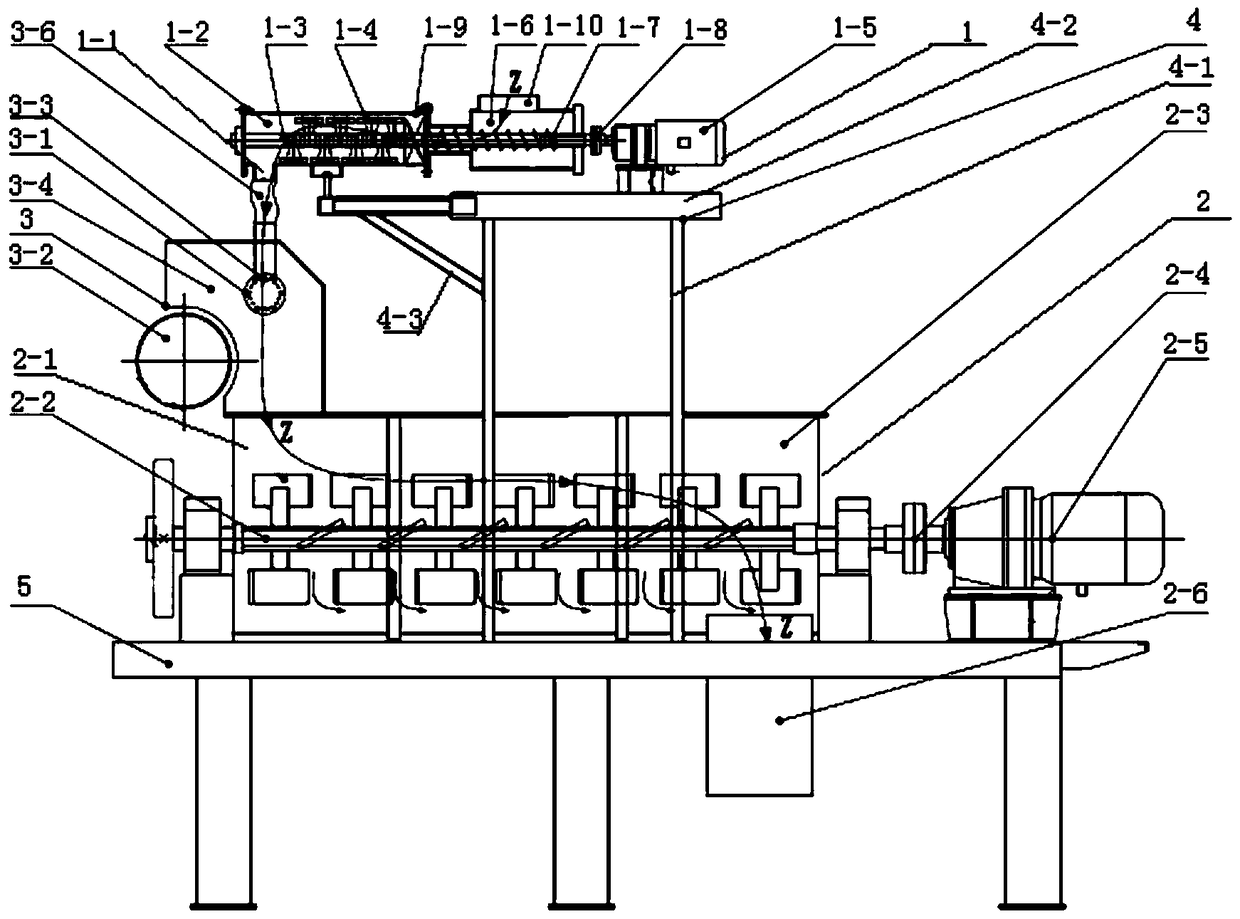
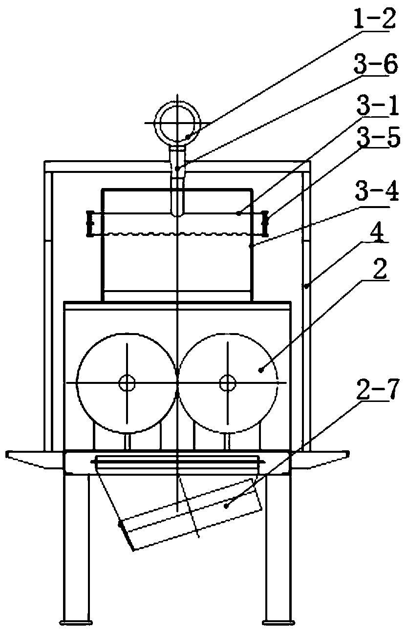
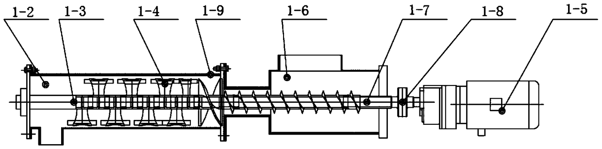
[0034] Comply with the above-mentioned technical scheme, see Figure 1-2 , the graded continuous stirring device of the present invention comprises a continuous single-shaft mixer 1 and a continuous double-shaft mixer 2, the continuous single-shaft mixer 1 is provided with a first-stage stirring outlet 1-1, and the continuous double-horizontal mixer The shaft mixer 2 is provided with a secondary stirring feed inlet 2-1, and the continuous single-horizontal shaft mixer 1 includes a primary mixing drum 1-2, and the primary mixing drum 1-2 is provided with a primary stirring shaft 1-3 , the primary stirring shaft 1-3 is distributed with primary stirring blades 1-4; the continuous twin-shaft mixer 2 is provided with a secondary stirring shaft 2-2; the continuous single-shaft mixer 1 and the continuous double-horizontal The shaft mixer 2 is connected through a conduction mechanism 3, which includes a blanking horizontal tube 3-1 and a feed pulley 3-2; 1-1 output, falling into the ...


PUM


Abstract

The invention discloses a staged continuous type stirring device and a stirring method. The staged continuous type stirring device comprises a continuous single horizontal shaft stirrer and a continuous double horizontal shaft stirrer, wherein the continuous single horizontal shaft stirrer is connected with the continuous double horizontal shaft stirrer through a conduction mechanism, and the conduction mechanism comprises a blanking horizontal pipe and a feeding belt wheel; powdery binding materials are output from a primary stirring discharge hole of the continuous single horizontal shaft stirrer, and drop into the continuous double horizontal shaft stirrer from a secondary stirring feeding port after passing through the blanking horizontal pipe in the conduction mechanism; and aggregates are transmitted into the continuous double horizontal shaft stirrer through the feeding belt wheel. The device provided by the invention is used for blending the powdery binding materials such as cement, lime and the like with water in a primary mixing drum, since no aggregate with relatively large particle size exist in a mixture, the barrier function to the aggregates is weakened, moreover, a strong shearing action formed during the high speed rotation process of an agitating vane can easily crush the aggregates, and enable the powdery binding materials to be sufficiently hydrated.

Description

technical field [0001] The invention belongs to the technical field of stabilized soil mixers, and relates to a step-by-step continuous mixing device and a mixing method. Background technique [0002] With the development of my country's economic construction, the traffic load on the highway is becoming more and more heavy; at the same time, the sustainable development of highway construction and the need to improve the durability of the pavement structure are becoming more and more urgent. Practice has shown that improving the construction quality of the base and subbase is conducive to improving the durability of the overall structure of the pavement and prolonging the service life. As the core part of the stabilized soil factory mixing equipment, the continuous forced mixer is directly related to the mixing quality of the finished stabilized soil material, and affects the construction quality of the pavement base layer. [0003] The existing stabilized soil mixer general...

Claims


Application Information

Patent Timeline
Patent Type & Authority Patents(China)
IPC IPC(8): B28C5/08B28C5/14B28C7/16
CPCB28C5/0818B28C5/0875B28C5/148B28C7/16
Inventor 赵利军邓欣申岩吴旭志惠梦梦冯忠绪赵悟
Owner CHANGAN UNIV
Why Eureka
Try Eureka