Fire preventing and extinguishing pulping device

A fire prevention and pulping technology, which is applied to mixers with rotating stirring devices, dissolving, mixers, etc., can solve the problems of slow mixing, easy to appear dead angles, and affect the use of slurry, so as to increase the speed, facilitate full mixing, The effect of improving uniformity

Pending Publication Date: 2021-11-05
HENAN UNIV OF URBAN CONSTR
View PDF0 Cites 0 Cited by
  • Summary
  • Abstract
  • Description
  • Claims
  • Application Information

AI Technical Summary

Problems solved by technology

[0003] The traditional pulping method is to use a high-pressure water gun to wash down the mud from the mound, flow into the mud ditch, remove the sundries, and then enter the mud mixing tank. After being stirred by the mixer, the slurry is formed and injected into the slurry delivery pipeline. This method cannot control the amount of water, so the concentration of the slurry cannot be controlled. Control, due to the short contact time of the pulping material with water, there is still a large amount of unmelted soil in the filtered slurry, the pulping effect is not ideal and the utilization rate of the pulping material is low, and in the cold area of ​​the north, it cannot be done outdoors. Scouring operation, and the external soil field and mixing tank occupy a large area, and the labor intensity of the workers is high
[0004] For this reason, some stirring and mixing equipment also appear on the mar

Method used


Image

  • Fire preventing and extinguishing pulping device
  • Fire preventing and extinguishing pulping device
  • Fire preventing and extinguishing pulping device

Examples


Embodiment approach

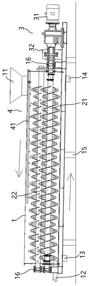
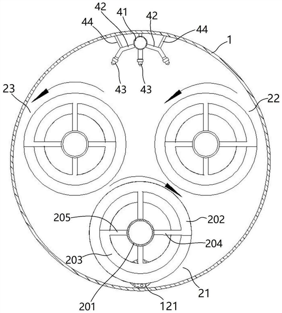
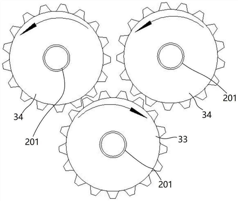
[0043] An embodiment of the anti-fire extinguishing pulping device of the present invention: as figure 1 As shown, the fire-proof pulping device includes a mixing drum 1 , a stirring and conveying mechanism, a driving mechanism 31 , a feeding mechanism, and a spraying device 4 . in:

[0044] The mixing drum 1 is a hollow cylindrical shell with a cylindrical mixing chamber, and the best choice is galvanized steel. The upper part of one end of the mixing drum 1 has a feed port 11, and the lower part of the other end is provided with a slurry outlet 12 and a first slag outlet 13. , the feed inlet 11 is provided with a material-receiving funnel, and the mixing cylinder 1 is inclined so that one end where the feed inlet 11 is set is lower than the other end where the slurry outlet 12 is set, and the inclination angle is 5-15°. The mixing cylinder 1 is set A second slag outlet 14 is provided at the lower part of one end of the feed inlet 11 . On-off valves are provided at the firs...


PUM


Abstract

The invention relates to a fire preventing and extinguishing pulping device. The device comprises a mixing barrel, a stirring and conveying mechanism, a driving mechanism, a feeding mechanism and a spraying device. The mixing barrel is obliquely arranged so that the end provided with the feeding port is lower than the other end provided with the slurry outlet, each of the three double-helical-ribbon stirring shafts comprises a rotating shaft rotationally assembled at the two ends of the mixing barrel and a double-helical-ribbon structure arranged around the rotating shaft, each double-helical-ribbon structure comprises two helical ribbons, the outer diameters of the two helical ribbons are different, the first double-helical-ribbon stirring shaft is located on the lower layer and close to the inner wall of the lower portion of the mixing barrel, the second double-helical-ribbon stirring shaft and the third double-helical-ribbon stirring shaft are located on the upper layer to form an inverted-delta-shaped arrangement structure, the rotating directions of the first double-helical-ribbon stirring shaft and the second double-helical-ribbon stirring shaft are opposite, and the rotating directions of the second double-helical-ribbon stirring shaft and the third double-helical-ribbon stirring shaft are the same, and materials on the upper layer and the lower layer are driven to flow in different directions; the spraying device is arranged at the upper part of the mixing barrel along the length direction of the mixing barrel. The device has the advantages of high pulping efficiency, uniform mixing during pulping and high pulp quality.

Description

technical field [0001] The invention relates to a fire-proof pulping device. Background technique [0002] Spontaneous combustion of pulverized coal in coal mines is one of the causes of coal mine fires. One of the solutions is to inject grout into the gobs of coal mines to isolate the pulverized coal from the air and solve the safety hazard of spontaneous combustion of pulverized coal. Coal mine grouting fire protection technology is to mix loess or fly ash, tailings, etc. with water in a certain proportion to make a uniform slurry, which is transported to the fire treatment area for grouting fire prevention. The pulping effect directly affects the reliability of fire protection, so the prerequisite for reliable fire protection in coal mines is that water and materials are fully and evenly mixed. [0003] The traditional pulping method is to use a high-pressure water gun to wash down the mud from the mound, flow into the mud ditch, remove the sundries, and then enter the m...

Claims


Application Information

Patent Timeline
IPC IPC(8): B01F7/08B01F15/02
Inventor 杨艳辉李中华黄玉峰李菲张路路万祥云娄全贾炳彭荣富黄战峰田好敏孙兰会杨豪王文军贾鑫涛刘向洋
Owner HENAN UNIV OF URBAN CONSTR
Why Eureka
Try Eureka