Cartridge mechanical seal device for corrosion-resistant pump

A technology of mechanical sealing device and corrosion-resistant pump, which is applied to components, mechanical equipment, pumps, etc. of pumping devices for elastic fluids, to achieve wide adaptability, reliable operation, and good sealing effect

Active Publication Date: 2016-08-24
安徽江南泵阀集团有限公司
View PDF5 Cites 0 Cited by
  • Summary
  • Abstract
  • Description
  • Claims
  • Application Information

AI Technical Summary

Problems solved by technology

However, the disclosed scheme of the above-mentioned patent application still has the problems of the basic structure of the existing corrosion-resistant pump cartridge mechanical seal.

Method used


Image

  • Cartridge mechanical seal device for corrosion-resistant pump
  • Cartridge mechanical seal device for corrosion-resistant pump
  • Cartridge mechanical seal device for corrosion-resistant pump

Examples


Embodiment 1

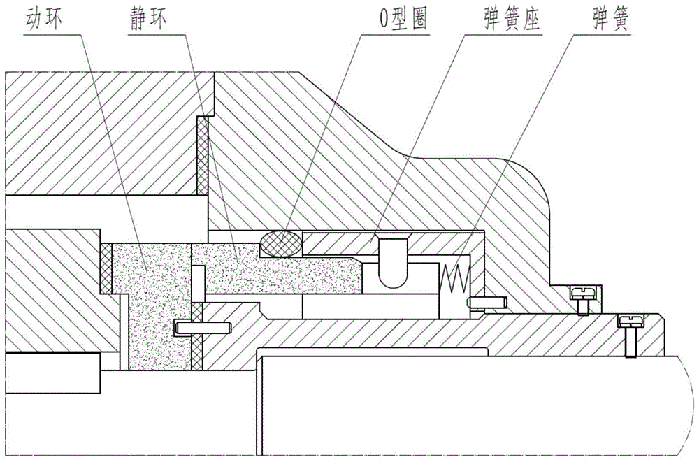
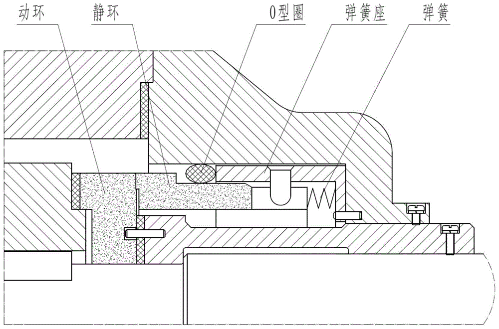
[0026] see image 3 , the corrosion-resistant pump cartridge mechanical seal device disclosed in the present invention is composed of a shaft sleeve 17, a gland 21, a medium end seal located inside the gland, and an atmospheric end water seal located outside the gland, wherein, The surface of the trumpet-shaped inner cavity of the gland 21 is lined with corrosion-resistant fluoroplastics; one end of the shaft sleeve 17 is coaxially installed in the inner cavity of the gland (21), and the medium end seal is sleeved, and the other The headgear is provided with the air end water seal, and is provided with two threaded holes on the outer peripheral surface for fixing screws on the pump shaft.

[0027] The medium end seal includes a moving ring 1, a static ring 2, a sliding sealing ring 4, a moving ring transmission pin 8, a spring seat 9 and a wave plate spring 11, wherein the moving ring 1 is fixed on the shaft sleeve 17 by the moving ring transmission pin On the end face of one...

Embodiment 2

[0035] see Figure 5 ~ Figure 6 The difference between the cartridge mechanical seal device for corrosion-resistant pumps described in this embodiment and Embodiment 1 is that the mouth of the inner cavity of the gland 21 expands radially outward to form a radially expanded portion, and the radially The surface of the expansion part is provided with an annular groove; the medium end seal also includes an anti-lock ring seal 3 and an anti-lock seal ring 7; wherein, the anti-lock seal ring 3 is embedded in the mouth of the inner cavity of the gland 21 In the radial expansion part, the sliding sealing ring 4 is covered therein, and the anti-lock sealing ring 7 is arranged in the annular groove, and the gap between the anti-lock sealing ring 3 and the surface of the inner cavity of the gland 21 is adjusted. seal.

[0036] The anti-lock sealing ring 3 is made of high-purity SiC industrial ceramics, and the material of the anti-lock sealing ring 7 is fluororubber.

[0037] The str...


PUM


Abstract

The invention relates to a seal of a liquid pump, in particular to a cartridge mechanical sealing device for an abrasion-resistant pump. The cartridge mechanical seal device consists of a shaft sleeve, a gland, a medium end seal and an atmosphere end water seal, wherein the medium end seal is positioned at the inner side of the gland, and the atmosphere end water seal is positioned at the outer side of the gland. The cartridge mechanical sealing device is characterized in that a wave plate spring is arranged between a spring seat and the gland, and the medium end seal further comprises an anti-seizure sealing ring and an anti-seizure sealing circle. The cartridge mechanical sealing device has the advantages that the problem of sealing failure of the gland or the sliding sealing circle between the anti-seizure sealing ring and a stationary ring because of the increase of a sealing cavity caused by the movement of the stationary ring in the running process of the pump is solved; the water seal is used at the atmosphere side, poisonous and harmful mediums, such as corrosive matters, are prevented from leaking into the atmosphere, the sealing effect is better, and the sealing surface at the medium side and the whole sealing cavity can be cooled, lubricated and flushed.

Description

technical field [0001] The invention relates to the sealing of liquid pumps, in particular to a cartridge type mechanical sealing device for liquid pumps. Background technique [0002] The cartridge mechanical seal is installed and combined with the main components such as the moving ring, static ring, spring, auxiliary sealing ring, bushing, gland and static sealing gasket at the non-maintenance site. The equipment can be replaced in time after the equipment is stopped, which simplifies The process of measurement and adjustment can not only reduce the time for on-site maintenance and save maintenance costs, but also improve the installation accuracy, ensure the sealing effect and prolong the service life. Therefore, cartridge mechanical seals have been widely used. [0003] In the existing mechanical seal device, the spring that pushes the static ring to compensate the abrasion of the moving ring and the static ring is installed between the static ring and the spring seat,...

Claims


Application Information

Patent Timeline
Patent Type & Authority Patents(China)
IPC IPC(8): F04D29/10
CPCF04D29/106F04D29/126
Inventor 吴敏吴同茂秦晓华吴虹胡敏
Owner 安徽江南泵阀集团有限公司
Why Eureka
Try Eureka