
Tensile fatigue and torsional fatigue testing machine for automobile parts

A technology for auto parts and torsional fatigue, which is applied in the field of tensile and torsional fatigue testing machines and fatigue testing machines, can solve the problems of poor versatility of equipment, complex structural connections, limited usability, etc., to reduce test costs, test accuracy, The effect of remarkable versatility

Inactive Publication Date: 2015-02-18
TONGJI UNIV
View PDF12 Cites 20 Cited by
  • Summary
  • Abstract
  • Description
  • Claims
  • Application Information

AI Technical Summary

Problems solved by technology

Although this invention can complete the test of the fatigue performance of the specimen material from tensile, bending, torsion single to multiaxial different combined loading conditions, its disadvantage is that its equipment has poor versatility and can only Applicable to test pieces of a certain shape or size
The Chinese utility model patent with the application number 200920196457.9 discloses a fatigue testing machine, which uses a crank rocker mechanism to connect the main output shaft with the main drive shaft, although it can effectively avoid driving The damage of the motor, but its structural connection is relatively complicated, and many parts are required. It can only be applied to the torsional fatigue test of the specimen, but not the tensile fatigue test. Its usability is limited, and the use of the crank rocker mechanism The accuracy of stability and test detection needs to be improved

Method used


Image

  • Tensile fatigue and torsional fatigue testing machine for automobile parts
  • Tensile fatigue and torsional fatigue testing machine for automobile parts
  • Tensile fatigue and torsional fatigue testing machine for automobile parts

Examples


Embodiment

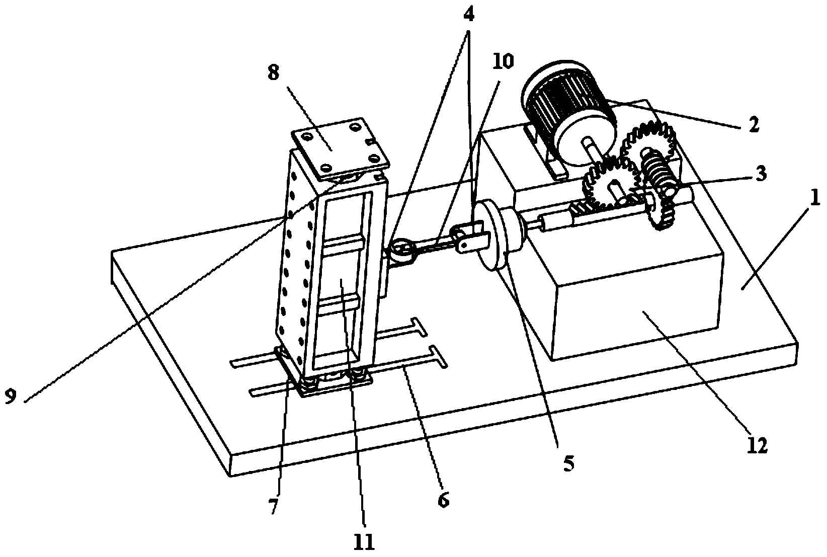
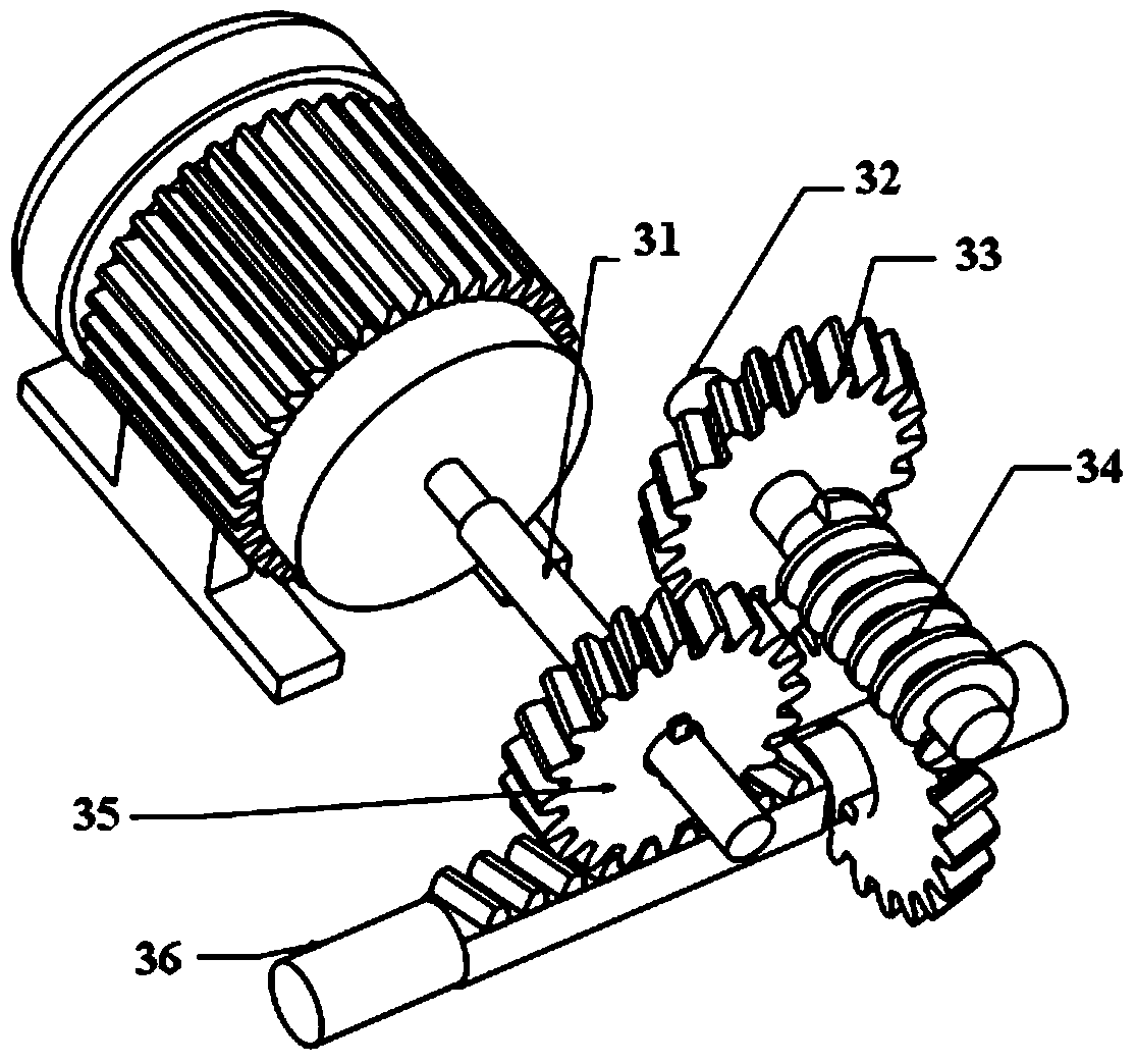
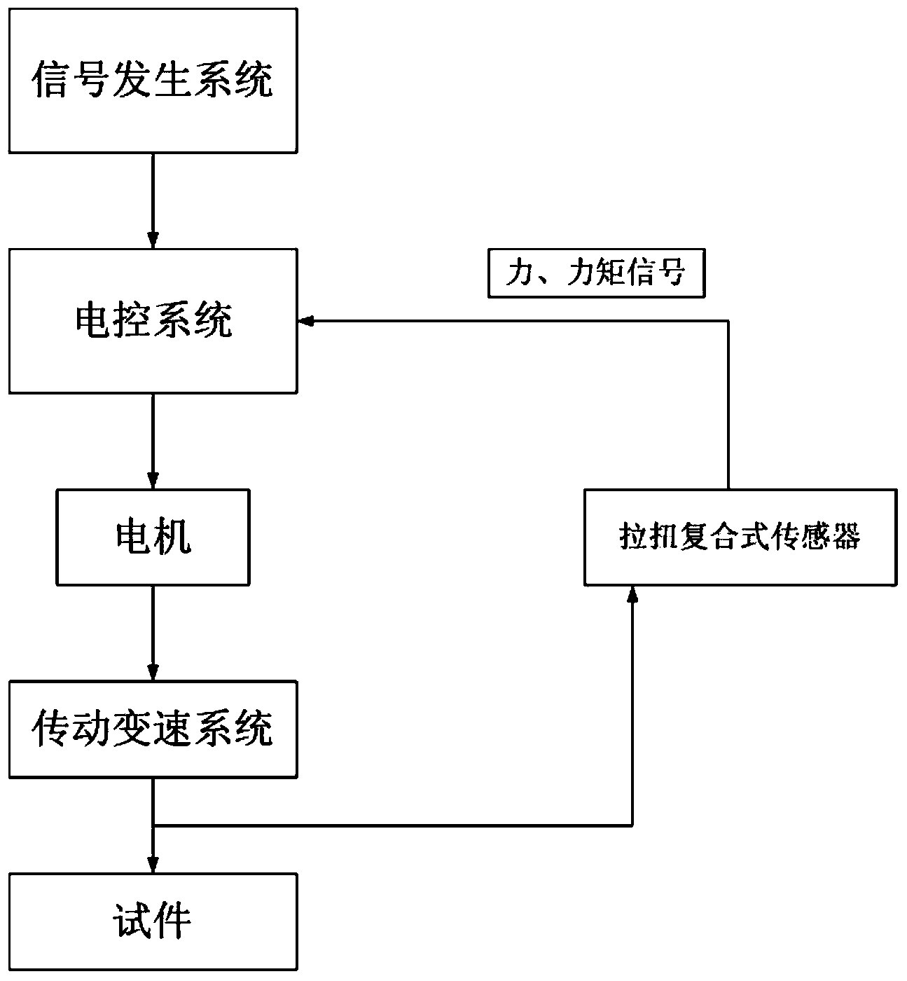
[0030] Such as Figure 1~2 As shown, a tensile and torsional fatigue testing machine for auto parts, the testing machine includes a support table 1, a motor 2, a test piece 10, a universal fixture 4, an installation column and a base 12, and the installation column and the base 12 are respectively They are oppositely arranged on the left and right sides of the support platform 1. The testing machine also includes an electric control system, a signal generation system, a tension-torsion compound sensor 5 and a transmission transmission system 3. The motor 2 and the transmission transmission system 3 are both arranged on the base. 12, the input end of the transmission variable speed system 3 is fixedly connected with the output shaft of the motor 2, and the output end is provided with a pull-twist composite sensor 5, and a pair of universal clamps 4 are arranged on the installation column and the pull-twist composite sensor 5 facing each other. Above, the test piece 10 is fixed ...


PUM


Abstract

The invention relates to a tensile fatigue and torsional fatigue testing machine for automobile parts. The tensile fatigue and torsional fatigue testing machine comprises a supporting platform, a motor, a test piece, a general fixture, an installing upright post, a base, an electronic control system, a signal generating system, a composite tension and torsion sensor and a transmission speed change system, wherein the motor and the transmission speed change system are arranged on the base; an input end of the transmission speed change system is fixedly connected with an output shaft of the motor; the composite tension and torsion sensor is arranged at an output end of the transmission speed change system; the composite tension and torsion sensor is connected with the electronic control system through a circuit; the signal generating system is sequentially connected with the electronic control system and the motor through a circuit. Compared with the prior art, the tensile fatigue and torsional fatigue testing machine has the advantages as follows: the tensile fatigue and torsional fatigue testing machine can conveniently perform a tensile fatigue test and a torsional fatigue test on the automobile parts, so that the periods for the fatigue tests are greatly shortened, and thus a basis for shortening the developing period of the whole automobile is provided.

Description

technical field [0001] The invention belongs to the technical field of mechanical processing and detection, and relates to a fatigue testing machine, in particular to a tensile and torsion fatigue testing machine used for auto parts. Background technique [0002] The durability of automobiles is an important performance of automobiles, and the fatigue test of auto parts is an important method to improve the durability of automobiles. Fatigue testing machine is an important instrument and equipment for testing the fatigue performance of materials, parts and structures. It is one of the most commonly used equipment for material performance testing in the material industry and quality supervision departments at all levels. However, most of the current fatigue testing machines are controlled by the hydraulic system, which makes the testing machine have technical defects such as large overall size, complex structure, and inaccurate control. Moreover, the cost of the hydraulic fat...

Claims


Application Information

Patent Timeline
IPC IPC(8): G01N3/26G01N3/32
Inventor 周鋐李冰杰金爽刘浩刘敏崔海洋朱旭铿
Owner TONGJI UNIV
Learn More