Combined shoe rack
A technology for combining shoe racks and shoe racks, which is applied in the field of shoe racks and can solve the problems of dust falling on shoes and wasting manpower and time
- Summary
- Abstract
- Description
- Claims
- Application Information
AI Technical Summary
Problems solved by technology
Method used
Image
Examples
specific Embodiment 1
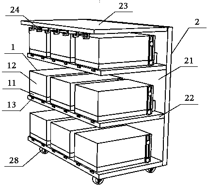
[0015] Such as figure 1 As shown, a combined shoe rack includes a shoe box 1 for placing shoes and a shoe rack 2 for placing the shoe box 1. The shoe rack 2 includes a back plate 21, a plurality of laminates 22 and a top plate 23. The shoe The box 1 includes a box bottom 11 and a box cover 12 , and a row of hooks 24 are arranged on the edge of the top plate 23 .
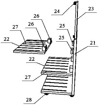
[0016] Such as figure 2 As shown, there are multiple rows and at least two blocks 25 are fixed on the backboard 21, and the edge of the laminate 22 has cards perpendicular to the laminate 22 and corresponding to the blocks 25 on the backplane 21. Groove 26, the card slot 26 allows the card block 25 to be inserted into it from top to bottom, and the laminate 22 is fixed on the back plate perpendicular to the back plate 21 .
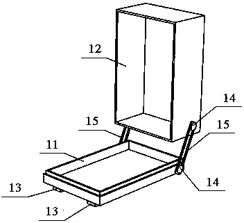
[0017] Such as image 3 As shown, the upper surface of the laminate 22 has a plurality of chute 27, the bottom surface of the box bottom 11 has a slider 13 that can slide in the chute 27, the...
specific Embodiment 2
[0018] Such as figure 1 As shown, a combined shoe rack includes a shoe box 1 for placing shoes and a shoe rack 2 for placing the shoe box 1. The shoe rack 2 includes a back plate 21, a plurality of laminates 22 and a top plate 23. The shoe The box 1 includes a box bottom 11 and a box cover 12 , and a row of hooks 24 are arranged on the edge of the top plate 23 .
[0019] Such as figure 2 As shown, there are multiple rows and at least two blocks 25 are fixed on the backboard 21, and the edge of the laminate 22 has cards perpendicular to the laminate 22 and corresponding to the blocks 25 on the backplane 21. Groove 26, the card slot 26 allows the card block 25 to be inserted into it from top to bottom, and the laminate 22 is fixed on the back plate perpendicular to the back plate 21 .
[0020] Such as image 3 As shown, the upper surface of the laminate 22 has a plurality of chute 27, the bottom surface of the box bottom 11 has a slider 13 that can slide in the chute 27, the...
specific Embodiment 3
[0022] Such as figure 1 As shown, a combined shoe rack includes a shoe box 1 for placing shoes and a shoe rack 2 for placing the shoe box 1. The shoe rack 2 includes a back plate 21, a plurality of laminates 22 and a top plate 23. The shoe The box 1 includes a box bottom 11 and a box cover 12 , and a row of hooks 24 are arranged on the edge of the top plate 23 .
[0023] Such as figure 2 As shown, there are multiple rows and at least two blocks 25 are fixed on the backboard 21, and the edge of the laminate 22 has cards perpendicular to the laminate 22 and corresponding to the blocks 25 on the backplane 21. Groove 26, the card slot 26 allows the card block 25 to be inserted into it from top to bottom, and the laminate 22 is fixed on the back plate perpendicular to the back plate 21 .
[0024] Such as image 3 As shown, the upper surface of the laminate 22 has a plurality of chute 27, the bottom surface of the box bottom 11 has a slider 13 that can slide in the chute 27, the...
PUM
 Abstract
Description
Claims
Application Information
 - R&D
- Intellectual Property
- Life Sciences
- Materials
- Tech Scout
- Unparalleled Data Quality
- Higher Quality Content
- 60% Fewer Hallucinations
Browse by: Latest US Patents, China's latest patents, Technical Efficacy Thesaurus, Application Domain, Technology Topic, Popular Technical Reports.
© 2025 PatSnap. All rights reserved.Legal|Privacy policy|Modern Slavery Act Transparency Statement|Sitemap|About US| Contact US: help@patsnap.com


