
Developer conveying device and image forming device

A conveying device and developer technology, applied to the electrical recording process using the charge pattern, the equipment and the instrument of the electric recording process using the charge pattern, etc., can solve the problems such as the reduction of the toner conveying capacity, and prevent the reduction of the conveying capacity Effect

Active Publication Date: 2019-11-15
OKI ELECTRIC IND CO LTD
View PDF6 Cites 0 Cited by
  • Summary
  • Abstract
  • Description
  • Claims
  • Application Information

AI Technical Summary

Problems solved by technology

[0006] However, in conventional printers, depending on the direction in which the plurality of fins of the prevention plate come into contact with the conveying screw, the toner on the shaft of the conveying screw sometimes enters between the shaft and the fins and is fixed on the shaft. The problem that the decrease in the conveyance ability of the toner cannot be sufficiently prevented yet

Method used


Image

  • Developer conveying device and image forming device
  • Developer conveying device and image forming device
  • Developer conveying device and image forming device

Examples


Embodiment approach 2

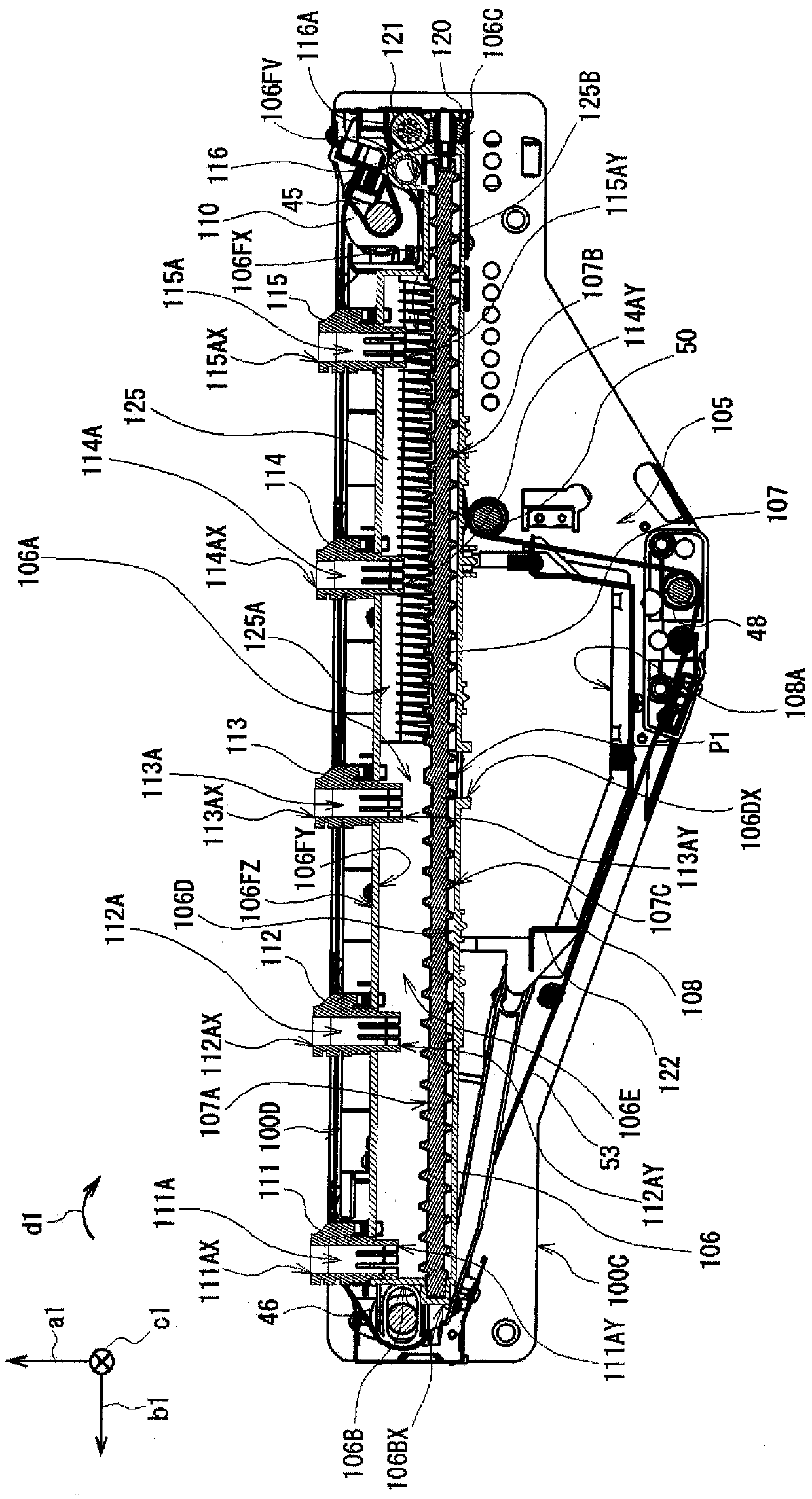
[0102] In addition, in the above-mentioned embodiment, the case where the plurality of toner removing fins 125B are formed in a flat plate shape in the toner removing portion 125 has been described, but the present invention is not limited thereto. Figure 13 As shown in (A), in the toner removing portion 133, the front ends of the plurality of toner removing fins 133A may be curved in an arc shape, and the back surface of the front ends may be pressed against the toner transport body 107. on the surface of the shaft portion 107A. and, if Figure 13 As shown in (B), in the toner removing portion 134 , the front ends of the plurality of toner removing fins 134A may be bent at a predetermined angle, and the front ends may be pressed against the shaft portion 107A of the toner conveying body 107 . on the surface.

[0103] In the present invention, with these configurations, as in the case of the above-mentioned embodiment, the tip ends of the plurality of toner removing fins 13...

Embodiment approach 3

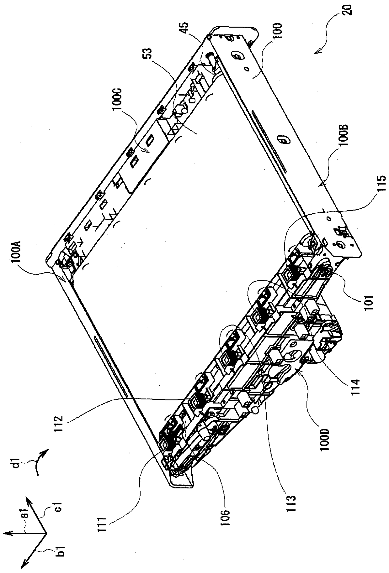
[0105] Furthermore, in the above-mentioned embodiment, a case has been described in which the toner removing portion is provided in the range from the front of the concave portion 106FX to the vicinity immediately above the toner discharge port 106DX in the toner recovery conveyance path 106A. 125, but it is not limited thereto. For example, it is also possible to lower the arrangement position of the transport path forming part 106 in the right side frame 100D so that it does not interfere with the bearing part 110 for the drive roller 45, so that the transport path forming part 106 The height of the internal space (that is, the height of the toner recovery conveyance path 106A) is uniform from the front end to the rear end, and the toner removing unit 125 is provided in the entire first conveyance range.

[0106] In addition, the present invention may be configured such that not only the toner removing unit 125 is provided in the toner recovery conveyance path 106A, but also ...

Embodiment approach 5

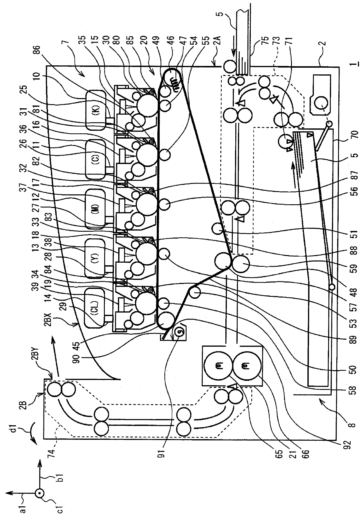
[0112] Furthermore, in the above-mentioned embodiments, it has been described that the image forming apparatus of the present invention is applied to Figure 1 to Figure 13 The color printer 1 described above is not limited thereto, and can be widely applied to image forming apparatuses of various configurations such as monochrome electrophotographic printers, multifunction printers, facsimile machines, multifunction machines, copiers, and the like.


PUM


Abstract

The developer conveying device and the image forming apparatus reliably prevent a reduction in the conveying ability of the developer. In the present invention, by providing the toner conveying body and the toner removing portion, when the waste toner is conveyed by the toner conveying body, the waste toner adhering to the surface of the shaft portion of the toner conveying body is removed. The toner removal fin hits the tip of the toner removal unit and sweeps it off. The toner conveying body is provided with a first screw blade on the surface of the shaft, and is supported so as to be able to send the toner to the toner. The toner conveying rotational direction rotates, and the toner removing portion presses the tip of the toner removing fin against the surface of the shaft portion of the toner conveying body in the opposite direction to the toner conveying rotational direction. The waste toner can be substantially reliably prevented from being fixed on the surface of the shaft portion of the toner conveying body, and the reduction in the conveying ability of the waste toner can be reliably prevented.

Description

technical field [0001] The present invention relates to a developer conveying device and an image forming device, and is preferably applied to, for example, an electrophotographic printer (hereinafter also referred to as a printer). Background technique [0002] Existing printers are provided with an elongated rectangular recovery container for recovering when an image formed on the surface of an image carrier by toner is transferred to the surface of transfer paper via an intermediate transfer belt. And the toner remaining on the surface of the image carrier is stored. [0003] In addition, the printer is provided with a transport screw in the recovery container so as to be rotatable parallel to the longitudinal direction of the recovery container, and the toner taken into the recovery container is transported by the rotation of the transport screw so that it spreads over the recovery container. inside the container. [0004] Moreover, in the printer, when the toner is fi...

Claims


Application Information

Patent Timeline
Patent Type & Authority Patents(China)
IPC IPC(8): G03G15/08
CPCG03G15/0879G03G15/0891G03G21/105G03G15/0844G03G2221/0005
Inventor 佐藤徹哉
Owner OKI ELECTRIC IND CO LTD
Learn More