Cleaning unit, process cartridge, and electrophotographic image forming apparatus

a technology of electrophotographic image and process cartridge, which is applied in the direction of electrographic process apparatus, optics, instruments, etc., can solve the problems of affecting the cleaning ability of the blade, affecting the production of background contamination of the final image, and abrasion of both the blade and the image carrier, so as to prevent the loss of the ion conductor

Inactive Publication Date: 2010-09-23
RICOH KK
View PDF2 Cites 21 Cited by
  • Summary
  • Abstract
  • Description
  • Claims
  • Application Information

AI Technical Summary

Benefits of technology

[0033]The polarity control member may further include an ion conductor. The cleaning unit may further include a blade supporting member to support the polarity control member, and a migration prevention layer between the polarity control member and the blade supporting member to prevent loss of the ion conductor.

Problems solved by technology

Further, residual toner remaining on the surface of the intermediate transfer member is also removed; otherwise, when the toner image is transferred from the intermediate transfer member onto a recording medium in a secondary transfer, residual toner remaining on the surface of the intermediate transfer member can be also transferred onto the surface of the recording medium, resulting in production of background contamination of the final image.
However, strongly pressing the blade against the image carrier accelerates abrasion of both the blade and the image carrier.
However, as time elapses, the cleaning ability of the blade is likely to deteriorate.
Moreover, pressing the blade against the image carrier with force necessitates a correspondingly large torque be generated by a motor for driving the image bearing member, necessitating a larger and more expensive motor.
However, this method has a serious drawback in that the high-voltage discharge generates not only ions but also ozone, which is harmful to humans and to the environment.
However, in the case of using a brush, the toner tends to adhere to the brush, partially blocking the discharging onto the surface to be biased to unify the polarity and making the polarity uncontrollable over time.
In the case of using a blade, the force of contact of the blade against the image carrier causes abrasive degradation in both the image carrier and the blade, which method is therefore problematic in terms of durability.
Therefore, this technique is not effective for toner the polarity of which cannot be controlled due to deterioration of the polarity control blade.
However, this approach does not enhance the cleaning ability and does not improve the durability of the cleaning unit.
However, since' a brush is used as the charging member, when a large amount of residual toner is conveyed thereto, the cleaning unit cannot collect the residual toner sufficiently, which can result in poor cleaning.
However, a gap is formed between the brushes, and therefore a large amount of residual toner remaining after transfer of a solid image cannot be cleaned sufficiently, and even the initial performance may become poor.
The most significant issue of the related-art cleaning unit using the polarity control member described above is poor durability in long-term image forming.
However, long-term image forming can cause the edge of the blade to be nicked or gouged, allowing toner to pass under the blade in streaks.
The inventors have found that, under these conditions, the toner cannot receive any polarity control, which can result in streaky cleaning defect.
Further, another disadvantage is that the toner that has managed to pass under the blade also tends to adhere to the surface of the blade.

Method used


Image

  • Cleaning unit, process cartridge, and electrophotographic image forming apparatus
  • Cleaning unit, process cartridge, and electrophotographic image forming apparatus
  • Cleaning unit, process cartridge, and electrophotographic image forming apparatus

Examples


Embodiment Construction

[0058]It will be understood that if an element or layer is referred to as being “on”, “against”, “connected to” or “coupled to” another element or layer, then it can be directly on, against, connected or coupled to the other element or layer, or intervening elements or layers may be present. In contrast, if an element is referred to as being “directly on”, “directly connected to” or “directly coupled to” another element or layer, then there are no intervening elements or layers present. Like numbers referred to like elements throughout. As used herein, the term “and / or” includes any and all combinations of one or more of the associated listed items.

[0059]Spatially relative terms, such as “beneath”, “below”, “lower”, “above”, “upper” and the like may be used herein for ease of description to describe one element or feature's relationship to another element(s) or feature(s) as illustrated in the figures. It will be understood that the spatially relative terms are intended to encompass...


PUM


Abstract

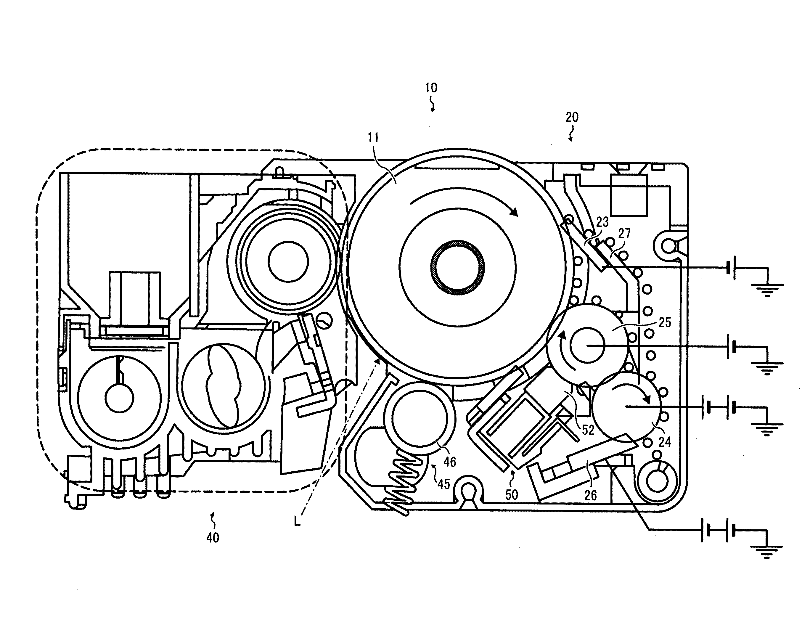
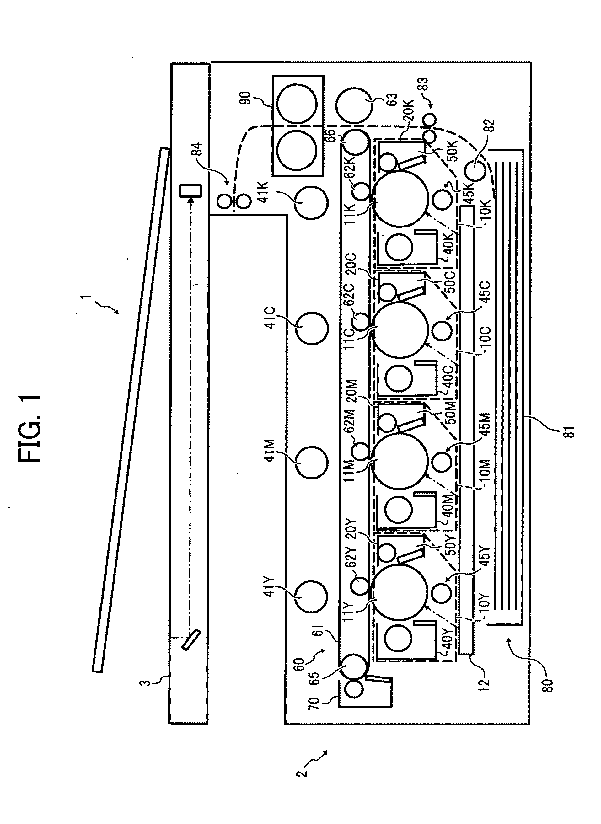
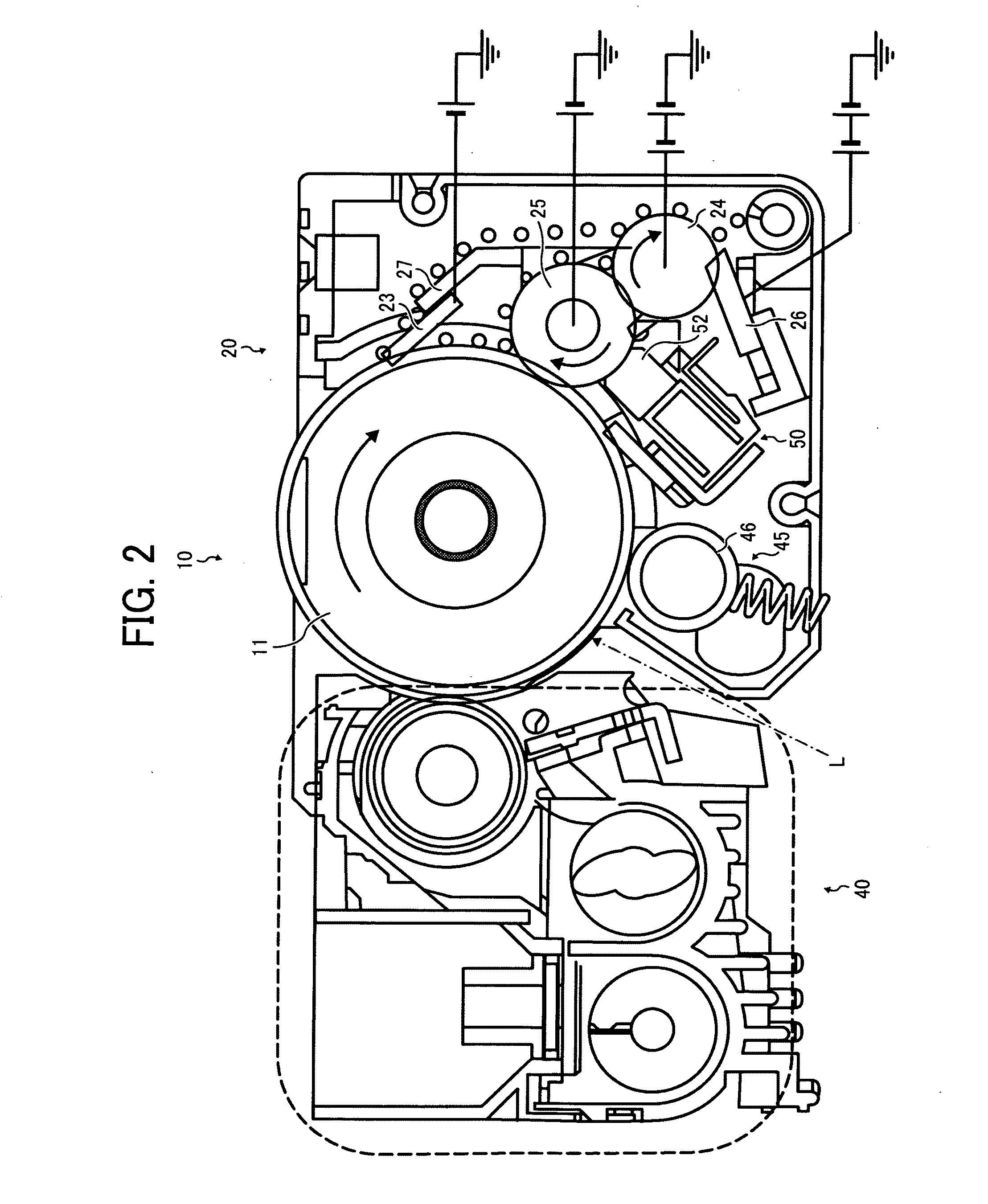
A cleaning unit that can remove particles of residual toner remaining on an image carrier after transfer and be incorporated in a process cartridge removably installable to an image forming apparatus, includes a brush roller disposed in contact with the image carrier to remove the residual toner remaining on the image carrier from the image carrier, and a polarity control member disposed in contact with the image carrier to control charge polarities of the residual toner remaining on the image carrier before the residual toner is removed by the brush roller. The polarity control member includes a first surface where the polarity control member contacts the image carrier, a second surface where the polarity control member does not contact the image carrier, and a conductive filler that is not exposed on the first surface that contacts the image carrier.

Description

CROSS-REFERENCE TO RELATED APPLICATIONS[0001]The present patent application claims priority pursuant to 35 U.S.C. §119 from Japanese Patent Application No. 2009-063728, filed on Mar. 17, 2009 in the Japan Patent Office, which is hereby incorporated by reference herein in its entirety.BACKGROUND OF THE INVENTION[0002]1. Field of the Invention[0003]Example embodiments of the present patent application relate to a cleaning unit, a process cartridge incorporating the cleaning unit, and an electrophotographic image forming apparatus incorporating the cleaning unit, and more particularly, to a cleaning unit used to clean an image carrier having an electrostatic latent image formed thereon by electrophotographic, electrostatic recording, or electrostatic printing methods and the like employed in a process cartridge and an electrophotographic image forming apparatus such as a copier, printer, facsimile machine, etc.[0004]2. Discussion of the Related Art[0005]Electrophotography is an image f...

Claims


Application Information

Patent Timeline
Patent Type & Authority Applications(United States)
IPC IPC(8): G03G21/10
CPCG03G2221/001G03G21/0035G03G21/0076
Inventor NARUSE, OSAMUYANO, HIDETOSHISUGIURA, KENJISUGIMOTO, NAOMINAKAMATSU, HIROKI
Owner RICOH KK
Why Eureka
Try Eureka