Implantable subcutaneous value for the treatment of hydrocephalus, and adjusting devices therefor

Inactive Publication Date: 2002-05-16
MARION BERNARD
View PDF4 Cites 21 Cited by
  • Summary
  • Abstract
  • Description
  • Claims
  • Application Information

AI Technical Summary

Benefits of technology

0021] The object of the present invention is therefore to resolve the above-mentioned drawbacks of providing a valve in which the position of th

Problems solved by technology

Unfortunately, that type of valve responds at a single predetermined pressure difference only, which means that a complete series of valves must be provided to a neurosurgical department to make it possible to operate on the variety of pressure ranges that is consistent with the various cases of hydrocephalus that are to be treated.
Another drawback of the valve described above is the diametral position of the rotor which extends across the valve body, i.e. across the flow of CSF, thus to some extent impeding the free flow of fluid through the valve from its inlet duct to its outlet duct.
As a consequence, as

Method used


Image

  • Implantable subcutaneous value for the treatment of hydrocephalus, and adjusting devices therefor
  • Implantable subcutaneous value for the treatment of hydrocephalus, and adjusting devices therefor
  • Implantable subcutaneous value for the treatment of hydrocephalus, and adjusting devices therefor

Examples


first embodiment

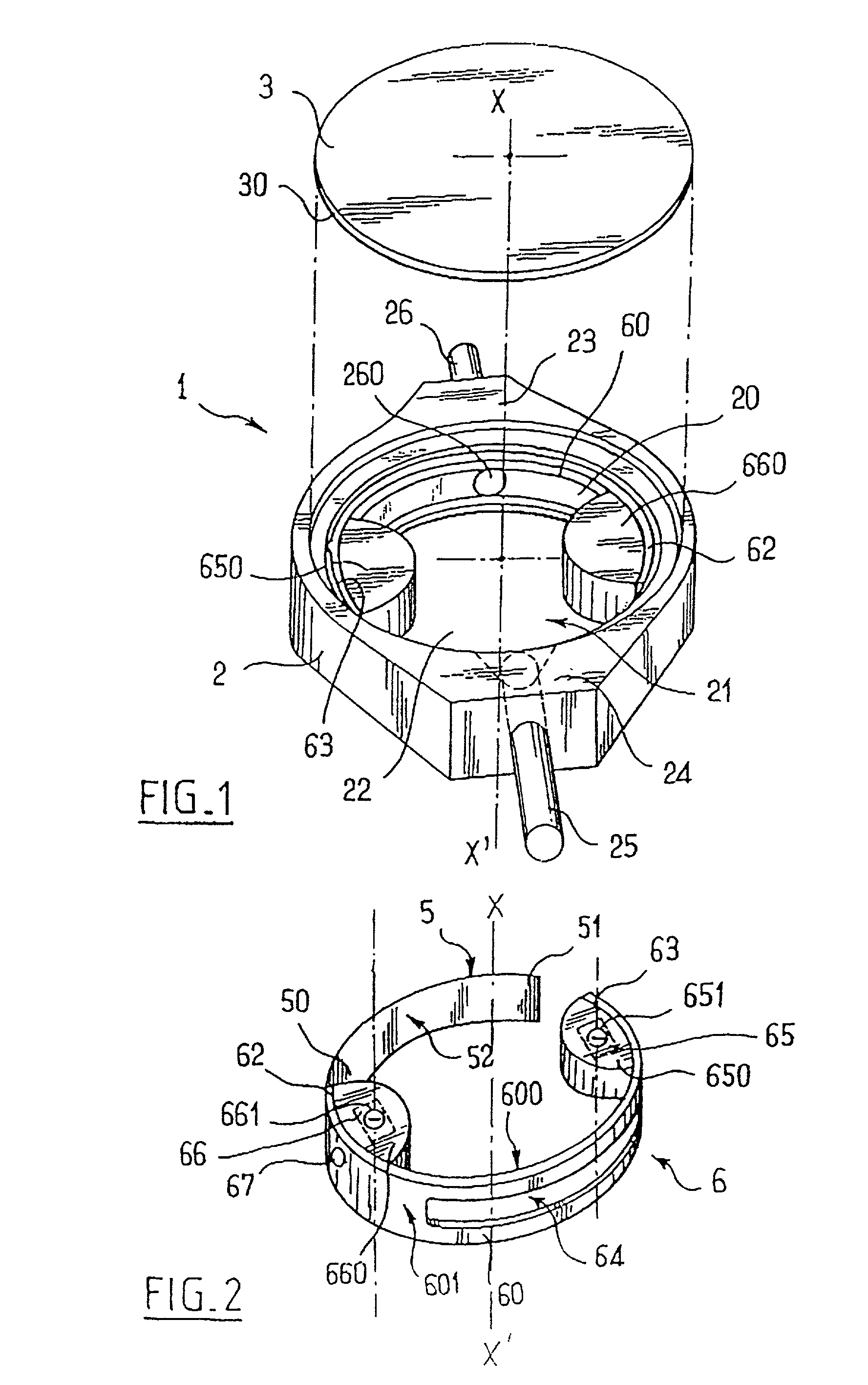
[0057] In a first embodiment as shown in FIG. 2, the two micromagnets have their respective same-sign poles 651 and 661 lying in a common upwardly-facing plane. As shown in FIG. 2, these two poles are negative, but they could equally well be positive.

[0058] This particular disposition of the magnets with same-sign poles lying in the same plane makes it possible to avoid the untimely turning effect which is inevitable when both poles belong to a single magnet and are therefore of opposite signs, particularly under the effect of a very strong magnetic field such as that used in NMR procedures.

[0059] By means of an external adjustment device that is described below, it is possible to act on the said micromagnets 65 and 66 from outside the valve to cause the arcuate blade 60 to turn about the central axis X-X' of the internal chamber. This central axis X-X' thus also constitutes an axis of rotation for the moving member 6.

[0060] Finally, as can be seen in FIGS. 2 to 4, the arcuate blade...

second embodiment

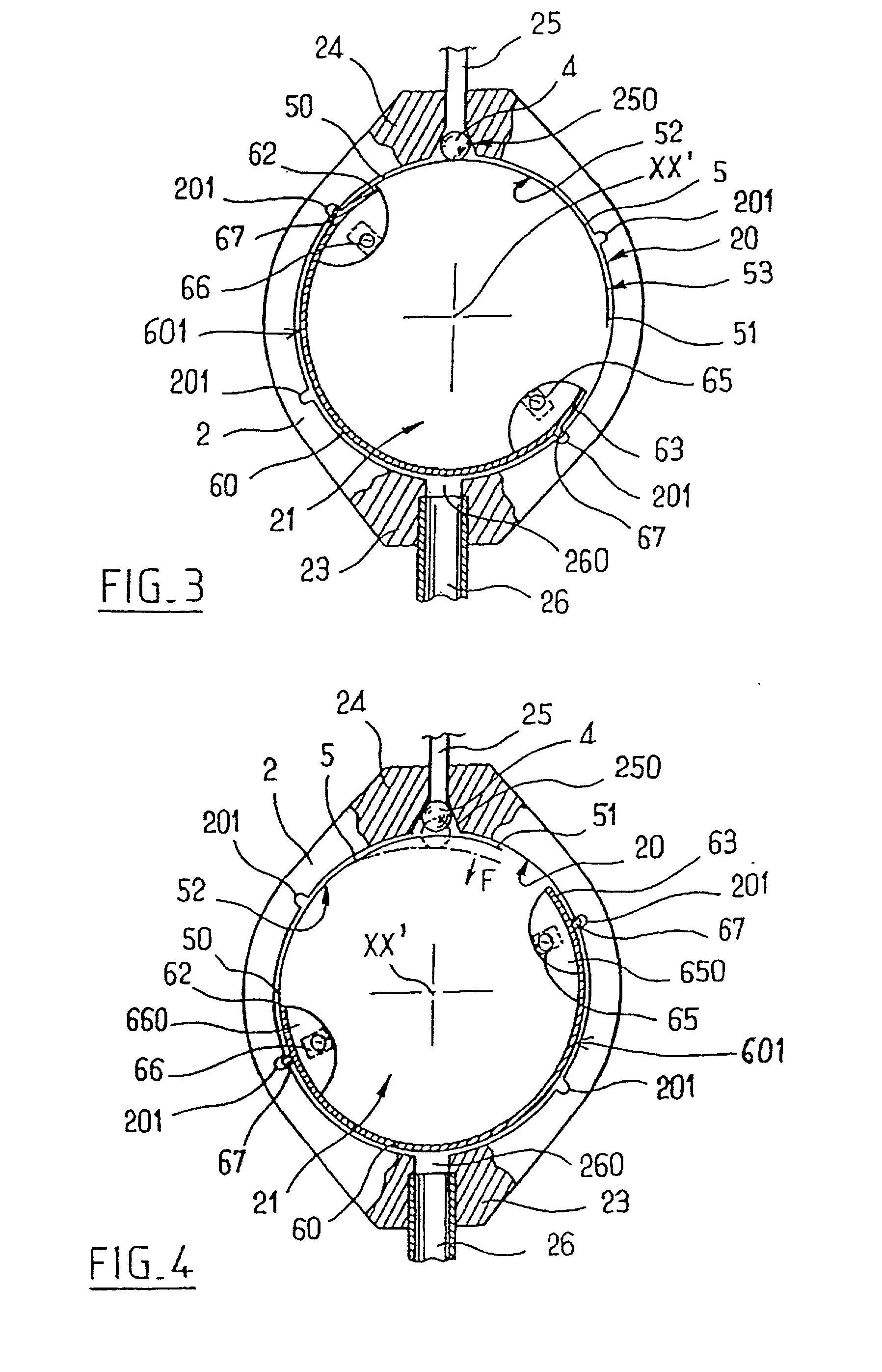
[0069] In a second embodiment which is not shown in the figures, the spring blade 5 has its end 50 fixed to the cylindrical wall 20 of the internal chamber, while its other end 51 is free. The spring blade 5 is also disposed in the configuration shown in FIG. 4 so that its free end 51 is close to the seat 250. Furthermore, the arcuate blade 60 is disposed in such a manner that its end 62, and in particular the plastics material block 660 can slide over the inside face 52 of the spring blade 5, bearing thereagainst so as to exert pressure thereon. Under such circumstances, it the position of the end 62 of the arcuate blade 60 which determines the opposing force applied by the spring blade 5.

[0070] The arcuate blade 60 is turned by means of an external adjustment device, and an embodiment thereof referenced 7 is shown in FIG. 5. For simplification purposes, this figure does not show the spring blade 5.

[0071] As can be seen in this figure, the adjustment device 7 comprises two strong c...


PUM


Abstract

The invention relates to a subcutaneous valve having opening pressure that can be adjusted non-invasively from the outside, said valve comprising a body presenting a chamber with a cylindrical inside side wall, an inlet duct and an outlet duct for cerebospinal fluid both opening out in said side wall, a valve member such as a ball placed at the inside end of said inlet duct, a spring blade fitting closely to the side wall of said chamber and urging the valve member against its seat, and a moving member controlled from the outside and provided with means for locking it in a determined position, the length of the spring blade acting on the valve member being determined by the position of said moving member. The valve is remarkable in that said moving member is constituted by a resilient flexible arcuate blade fitting closely to the cylindrical inside wall of said chamber. The valve is applicable to the treatment of hydrocephalus.

Description

[0001] The present invention relates to surgically-implantable valves used for the treatment of hydrocephalus by regulating cerebrospinal fluid (CSF), and it also relates to a device for adjusting the opening pressure of said valve from the outside, i.e. through skin tissue.[0002] It has been known for more than fifty years that one of the major causes of hydrocephalus is a disturbance or blockage of the natural sites for resorbing CSF, namely the arachnoid villosities.[0003] In normal adults, the brain is maintained at a constant hydrostatic pressure inside the cranial cavity by means of the self-adjusting mechanism of the arachnoid villosities that open and close appropriately to maintain a constant pressure gradient inside the cerebral ventricles. As a result, any disturbance in CSF resorption will simultaneously give rise to an increase in the volume of the cerebral ventricles, and in most cases to an increase in intraventricular pressure.[0004] In newborns whose frontanelles ar...

Claims


Application Information

Patent Timeline
IPC IPC(8): A61M27/00
CPCA61M27/006Y10T137/7873
Inventor MARION, BERNARD
Owner MARION BERNARD
Why Eureka
Try Eureka