
Auxiliary lifting device for steam turbine high pressure valve assembly

A lifting device and high-pressure valve technology, applied in the direction of transportation and packaging, load hanging components, etc., can solve the problems of heavy preparation work, insufficient clamping force, and unstable lifting process, so as to save time and secure the clamping force Effect

Active Publication Date: 2016-05-04
HARBIN TURBINE +1
View PDF6 Cites 1 Cited by
  • Summary
  • Abstract
  • Description
  • Claims
  • Application Information

AI Technical Summary

Problems solved by technology

[0003] The purpose of the present invention is to provide an auxiliary lifting device for the assembly of the high-pressure valve of the steam turbine, so as to solve the problem that the existing lifting method when the high-pressure regulating valve of the steam turbine is assembled is directly tied with a sling for lifting, and there is a large amount of preparation work before lifting, and the lifting process is difficult. It is not stable, which leads to potential safety hazards, and the clamping force is not enough, so that the lifting rope is easy to loosen, resulting in bumping and damage to the high-pressure regulating valve of the steam turbine

Method used


Image

  • Auxiliary lifting device for steam turbine high pressure valve assembly
  • Auxiliary lifting device for steam turbine high pressure valve assembly
  • Auxiliary lifting device for steam turbine high pressure valve assembly

Examples


specific Embodiment approach 1

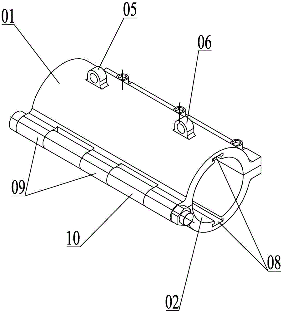
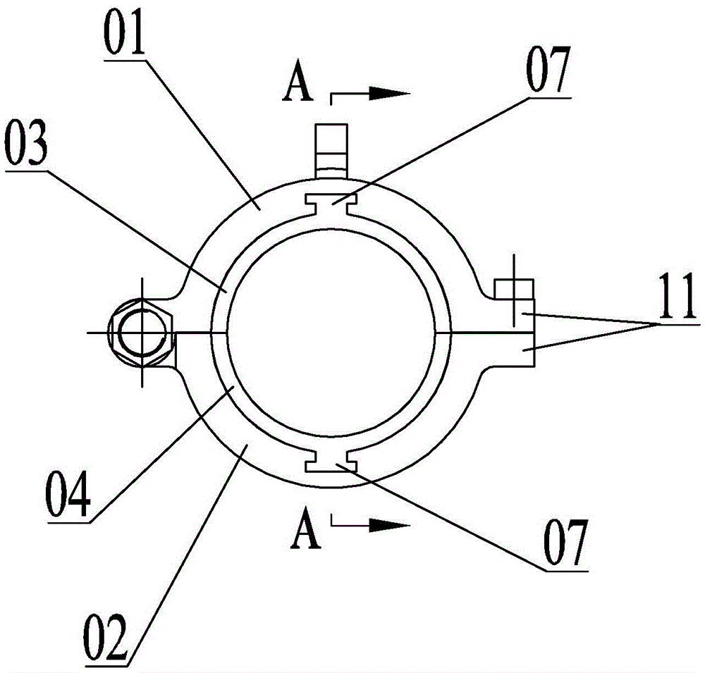
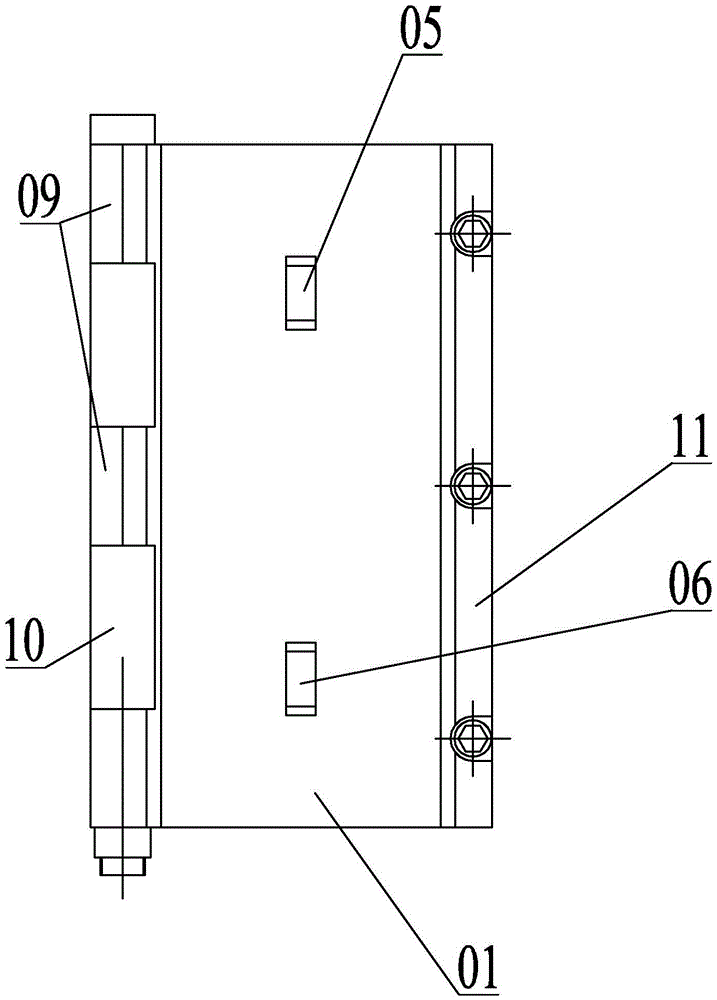
[0016] Specific implementation mode one: combine Figure 1 to Figure 6 Explain that the auxiliary lifting device for the assembly of the steam turbine high-pressure valve in this embodiment includes an upper casing 01, a lower casing 02, an upper lining tile 03, a lower lining tile 04, a lifting lug 05 and a lifting lug 2 06,

[0017] The cavity of the upper case 01 is opened on the bottom surface of the upper case 01 and penetrates the upper case 01 horizontally, and the cavity of the lower case 02 is opened on the top surface of the lower case 02 and penetrates the lower case 02 horizontally. The bottom surface of the shell 01 is attached to the top surface of the lower shell 02, the cavity of the upper shell 01 is set opposite to the cavity of the lower shell 02, the upper shell 01 is movably connected with the lower shell 02, and the upper lining tile 03 It is detachably fixed in the cavity of the upper casing 01, and the lower lining tile 04 is detachably fixed in the cav...

specific Embodiment approach 2

[0019] Specific implementation mode two: combination Figure 1 to Figure 6 Explain that the upper casing 01 and the lower casing 02 of this embodiment are both horizontally arranged cylinders with a semicircular cross-section, the horizontal surface of the upper casing 01 is the bottom surface, the horizontal surface of the lower casing 02 is the top surface, and the upper casing 02 is the top surface. The shape of the tile 03 is consistent with the shape of the upper casing 01, and the shape of the lower lining tile 04 is consistent with that of the lower casing 02.

[0020] The undisclosed technical features in this embodiment are the same as those in the first embodiment.

specific Embodiment approach 3

[0021] Specific implementation mode three: combination Figure 1 to Figure 6 Explain that the outer arc surface of the upper lining tile 03 and the outer arc surface of the lower lining tile 04 in this embodiment are fixed with T-shaped keys 07, the inner arc surface of the upper casing 01 and the inner circle of the lower casing 02 There are T-shaped grooves 08 on the arc surface, the T-shaped key 07 of the upper lining tile 03 is matched with the T-shaped groove 08 of the upper shell 01, and the T-shaped key 07 of the lower lining tile 04 is matched with the T-shaped groove of the lower shell 02. 08, the T-shaped slot 08 is set on one end surface of the upper shell 01 and is not penetrated along the axis of the upper shell 01, and the T-shaped slot 08 is set on one end surface of the lower shell 02 and is not penetrated along the axis of the lower shell 02 open.

[0022] In this embodiment, the T-shaped groove 08 is not opened through, so that the positioning of the T-shape...


PUM


Abstract

The invention provides an auxiliary hoisting device applied to the assembly of a turbine high-pressure valve, relates to an auxiliary hoisting device applied to the assembly of a turbine valve, and aims to solve the problems that when the conventional turbine high-pressure regulating valve is directly bundled by lifting ropes to be hoisted during valve assembly, the preparation workload before hoisting is large, the hoisting process is unstable, so that the potential safety hazard is easy to generate, and the clamping force is insufficiently large, the lifting ropes are easy to loosen and the valve is bumped and damaged. A mold cavity of an upper shell horizontally penetrates through the upper shell, a mold cavity of a lower shell horizontally penetrates through the lower shell, the upper shell and the lower shell are adhered, the mold cavity of the upper shell and the mold cavity of the lower shell are arranged oppositely, the upper shell and the lower shell are connected, an upper lining tile is fixedly connected with the interior of the mold cavity of the upper shell, a lower lining tile is fixedly connected with the interior of the mold cavity of the lower shell, the upper lining tile and the lower lining tile are arranged oppositely, a turbine high-pressure valve is respectively matched with the upper lining tile and the lower lining tile, and a lifting lug I and a lifting lug II are fixedly connected with the top of the upper shell. The auxiliary hoisting device disclosed by the invention is applied to the hoisting of the turbine high-pressure valve.

Description

technical field [0001] The invention relates to an auxiliary lifting device for steam turbine valve assembly. Background technique [0002] The structure of the steam turbine high-pressure regulating valve is complex and consists of many parts, including many shafts and sleeves. The existing lifting method when assembling the high-pressure regulating valve of the steam turbine is directly tied up with a sling for lifting. Since the high-pressure regulating valve of the steam turbine does not have a lifting fixed point, the preparation workload before lifting is heavy, and the lifting process is not stable, resulting in potential safety hazards and clamping. If the force is not enough, the lifting rope is easy to loosen and the high-pressure regulating valve of the steam turbine is bumped and damaged. Contents of the invention [0003] The purpose of the present invention is to provide an auxiliary lifting device for the assembly of the high-pressure valve of the steam tur...

Claims


Application Information

Patent Timeline
Patent Type & Authority Patents(China)
IPC IPC(8): B66C1/10
CPCB66C1/10
Inventor 车延超高伟王文丹栾晓忠高岩李久雷王其江郁洪光张德宇
Owner HARBIN TURBINE
Learn More