Transient stability control system and method for ultrahigh voltage AC/ DC transmission system
A DC power transmission system and power transmission system technology, applied in control systems, control generators, power transmission AC networks, etc., can solve the problems of over-limit fluctuations, power angle transient instability voltage, etc., and achieve the effect of compensating for voltage drops
- Summary
- Abstract
- Description
- Claims
- Application Information
AI Technical Summary
Problems solved by technology
Method used
Image

Examples
Embodiment Construction
[0021] The present invention will be further introduced below in conjunction with the accompanying drawings and specific embodiments.
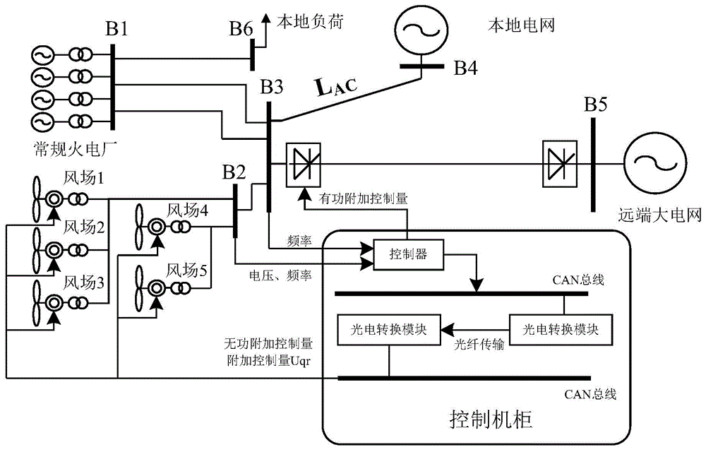
[0022] Such as figure 1 Shown is the structural diagram of the implementation of the transient stability control system of the UHV AC-DC transmission system of the present invention. It can be seen from the figure that the system includes a DC transmission sending end control system (not shown in the figure) for controlling and managing the DC transmission system. ) and the double-fed fan excitation inverter control system for controlling and managing the wind farm, and also includes the wind farm wide-area control system for the coordinated control of the DC transmission system sending end control system and the double-fed fan excitation inverter control system; The wind farm wide-area control system includes a controller, which is used to receive the sending end frequency of the DC transmission system and the common bus voltage frequency and...
PUM
 Abstract
Description
Claims
Application Information
PatSnap Eureka turns technology decisions into work you can execute. Powered by our Innovation Knowledge Graph, it runs expert workflows across engineering, life sciences, materials and intellectual property. Get your review-ready output in minutes.


