Stirring device

A technology of stirring device and stirring body, which is applied to mixers with rotating stirring devices, mixer accessories, transportation and packaging, etc., which can solve the problems of reduced efficiency and complicated mechanism, and achieve the effect of simple structure

Active Publication Date: 2015-03-04
MITUYATEC +1
View PDF6 Cites 3 Cited by
  • Summary
  • Abstract
  • Description
  • Claims
  • Application Information

AI Technical Summary

Problems solved by technology

However, the mechanisms in the above-mentioned Patent Documents 1 and 2 are relatively complicated and are not mechanical direct power transmission, so there is a problem that the efficiency is lowered.

Method used


Image

  • Stirring device
  • Stirring device
  • Stirring device

Examples


Embodiment Construction

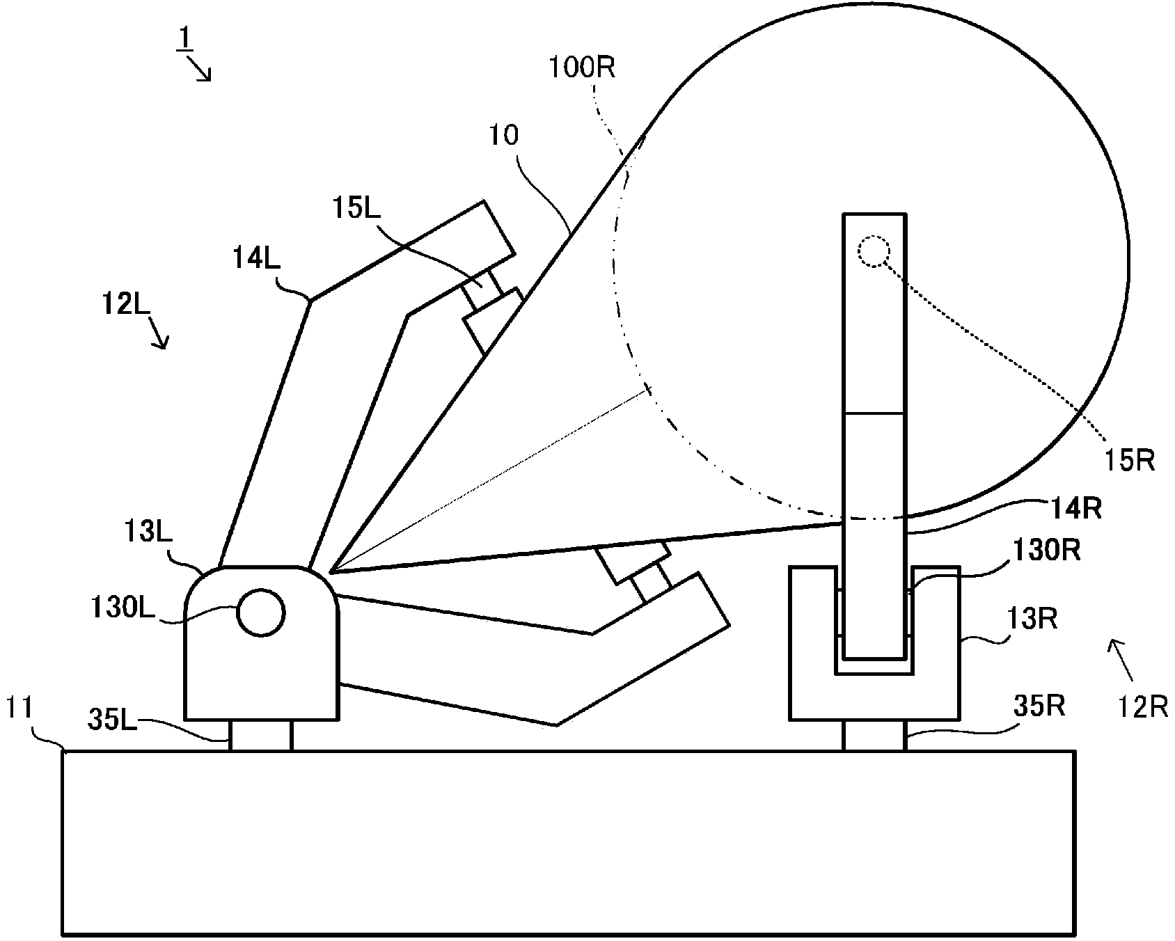
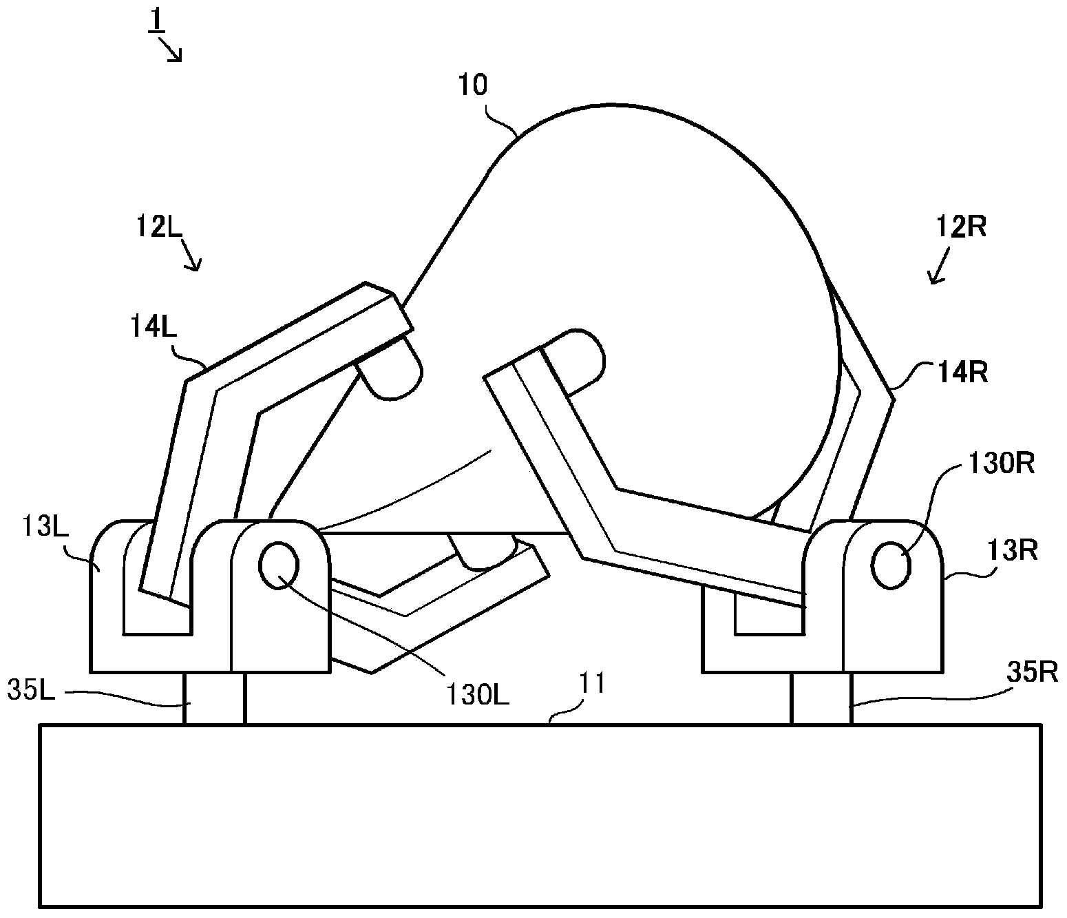
[0048] Hereinafter, a stirring device according to an embodiment of the present invention will be described with reference to the drawings. figure 1 is the front view of the stirring device. The stirring device 1 is installed in a liquid, and has a stirring body 10 , a support stand 11 , universal joints 12L, 12R, and a drive mechanism 30 built in the support stand 11 .

[0049] It should be noted that in the following description, the figure 1 Up, down, left, and right in the shown stirring device 1 are referred to as up, down, left, and right, respectively, the back direction of the paper is called the back side, and the front side of the paper is called the front.

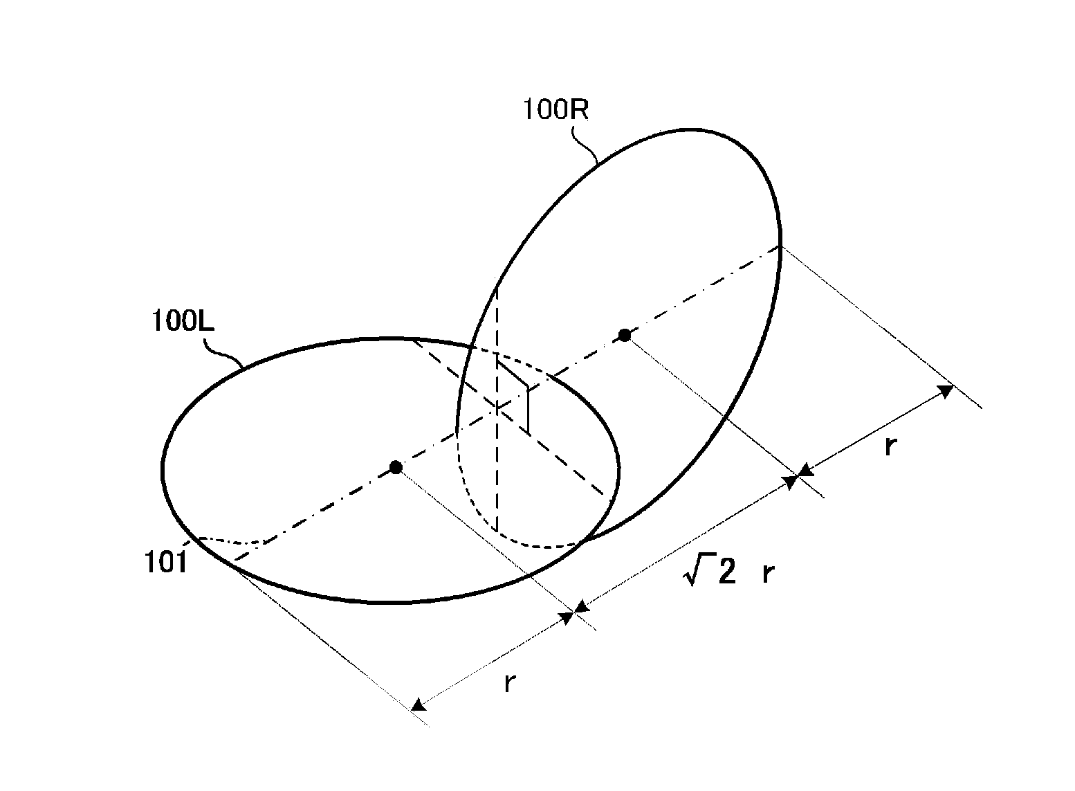
[0050] The stirring body 10 is a smooth three-dimensional supported on the supporting platform 11 by means of universal joints 12L, 12R, and is figure 2 The convex-hull solid of the double stroke roller shown (solid surrounded by line segments connecting ground points). The stirring body 10 is driven by the ...


PUM


Abstract

Provided is a stirring device that can drive a stirring body with a simple structure and without applying excessive force. The stirring device is provided with: the stirring body, which is a two-circle roller having an axis of rotation and two stirring fins; first and second drive shafts with axial centers not matching the axis of rotation; a first axial joint, which connects the first drive shaft on a first stirring fin side of the axis of rotation; a second axial joint, which connects the second drive shaft on a second stirring fin side of the axis of rotation; and a drive unit that exclusively carries out rotary drive of only either one of the first and second drive shafts. The drive unit is provided with a regulating member that makes a tooth part of a first gear face a drive side gear without play at a rotary position where the boundary between the tooth part and a toothless part of the first gear faces the drive side gear and makes a tooth part of a second gear face the drive side gear without play at a rotary position where the boundary between the tooth part and a toothless part of the second gear faces the drive side gear.

Description

technical field [0001] The invention relates to a stirring device for stirring liquid. Background technique [0002] As shown in Patent Documents 1 and 2, there has been proposed a device for stirring a liquid by rotating and swinging a stirring body. In the stirring device of this aspect, since the liquid is stirred by the complicated rotational swing motion of the stirring body, the liquid can be stirred efficiently with a small electric power. [0003] prior art literature [0004] patent documents [0005] Patent Document 1: Japanese Patent Application Laid-Open No. 61-74962 [0006] Patent Document 2: Japanese Patent Laid-Open No. 2002-143665 [0007] The problem to be solved by the invention [0008] The above-mentioned stirring device supports the left and right sides of the stirring body with universal joints, and the rotation of the left and right drive shafts is transmitted to the stirring body through the left and right universal joints, thereby causing the s...

Claims


Application Information

Patent Timeline
Patent Type & Authority Applications(China)
IPC IPC(8): B01F11/00
CPCB01F11/0097B01F31/70B01F35/3204B01F27/212B01F27/213B01F35/31B01F35/322
Inventor 山本善和菅原广树
Owner MITUYATEC
Why Eureka
Try Eureka