Brake fluid container with pressure equalization

A technology of brake fluid and container, applied in the direction of hydraulic brake transmission, etc., can solve the problems of complex manufacturing and high cost, and achieve the effect of avoiding pressure drop

Active Publication Date: 2017-03-01
ROBERT BOSCH GMBH
View PDF5 Cites 0 Cited by
  • Summary
  • Abstract
  • Description
  • Claims
  • Application Information

AI Technical Summary

Problems solved by technology

[0005] The disadvantage of this solution is the complex manufacture and the overall relatively high costs of the additional installation operations

Method used


Image

  • Brake fluid container with pressure equalization
  • Brake fluid container with pressure equalization
  • Brake fluid container with pressure equalization

Examples


Embodiment Construction

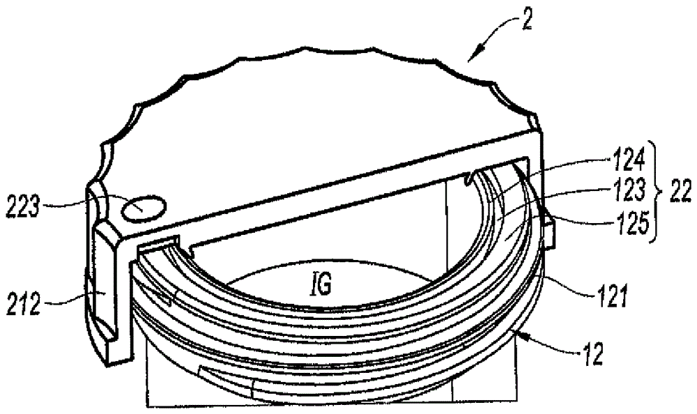
[0033] according to figure 1 , the brake fluid container 1 shown very partially has an upper part 11 with a threaded neck 12 closed by a screwed plug 2 for allowing filling of the container while ensuring equalization of pressure inside the container. The balancing should be done quickly while the brake system is running, so that this pressure is at atmospheric pressure with rapid pumping of brake fluid, to avoid pressure drops that would block the pumping of brake fluid by the master cylinder, the master The cylinder is fed from container 1 .

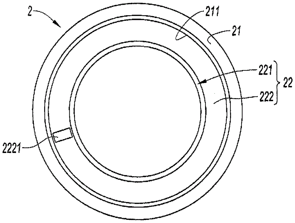
[0034] The bung 2 has a rim 21 with an internal thread 211 corresponding to the thread 121 of the neck 12 and a bottom 22 . On the outside, the bung 2 is provided with raised portions 212 to facilitate gripping for fastening or loosening.

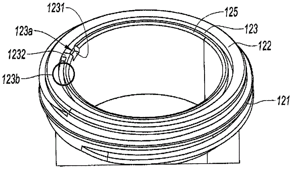
[0035] according to figure 2 , the neck 12 includes an upper portion 122 on the other side of the external thread 121 , and the upper portion 122 has an upwardly opening balancing groove 123 on ...


PUM


Abstract

A brake fluid reservoir includes in its upper portion a bottleneck with a thread and a top for receiving a cap with an edge and a top. The top of the bottleneck has channel opens into the atmosphere, one end of the channel leading into the atmosphere, one end of the channel leading into the interior of the bottleneck and the other end communicating with the outside atmosphere via a cavity.

Description

technical field [0001] The invention relates to a brake fluid container with mise à l'air for its pressure equalization, the upper part of the container body being equipped with a threaded neck receiving a threaded stopper and includes a baffled passage for the container to atmosphere. Background technique [0002] It is known to implement brake fluid containers with pressure equalization. There are different embodiments of the container, in which the cover comprises elements forming a deflector, which allow the pressure balance. These solutions are not always satisfactory, however, since the risk of liquid escaping due to the orientation of the deflector, which may be in the wrong direction relative to the axis of the vehicle, remains. [0003] Document EP 2 189 344 describes a brake fluid container with a pressure equalization device, which allows to avoid the risk of brake fluid escaping in abnormal situations by means of a special direction of the outlet of the plug, ...

Claims


Application Information

Patent Timeline
Patent Type & Authority Patents(China)
IPC IPC(8): B60T11/26
CPCB60T11/26
Inventor V.莫里J-M.洛S.伦茨纳
Owner ROBERT BOSCH GMBH
Why Eureka
Try Eureka