
Crimping tool for wire end ferrules

一种压接工具、压接模具的技术,应用在制造工具、线路/集电器零部件、连接等方向

Active Publication Date: 2015-03-04
WEIDMUELLER INTERFACE GMBH & CO KG
View PDF6 Cites 5 Cited by
  • Summary
  • Abstract
  • Description
  • Claims
  • Application Information

AI Technical Summary

Problems solved by technology

[0003] However, the force-stroke-compensation device realized in this way allows only a very limited range of diameters for the core wire end sleeves that can be squeezed in the pliers

Method used


Image

  • Crimping tool for wire end ferrules
  • Crimping tool for wire end ferrules
  • Crimping tool for wire end ferrules

Examples


Embodiment Construction

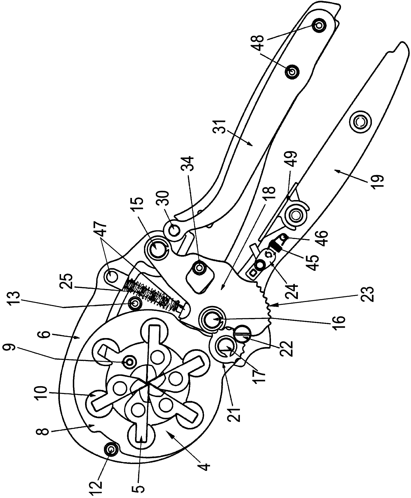
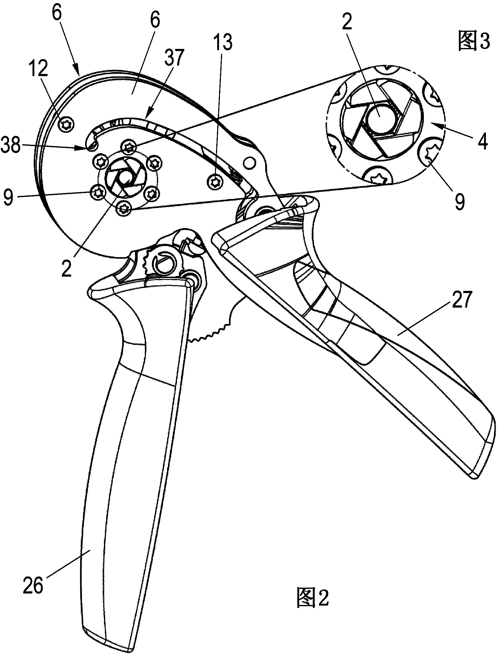
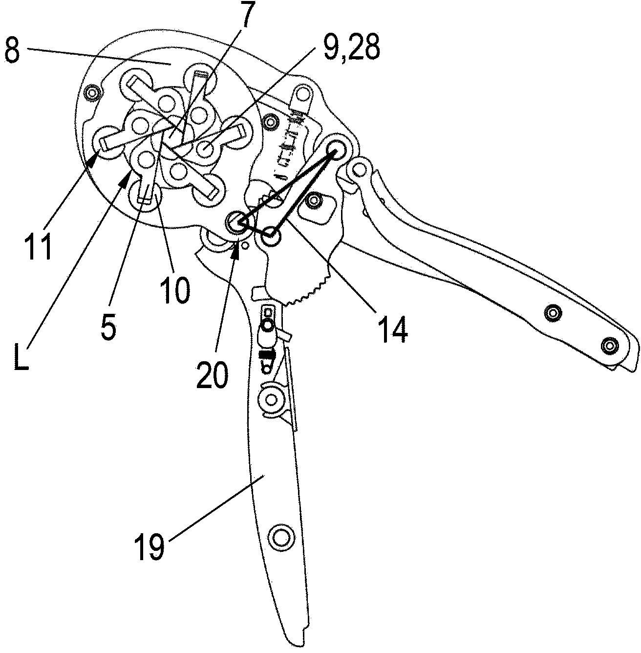
[0030] figure 1 A crimping tool 1 according to the invention is shown for crimping wire end sleeves 2 (not shown), contact bushings, cable lugs or the like on electrical conductors 3 (not shown). The manually operated crimping tool 1 in the form of pliers comprises a crimping die 4 with automatic adjustment according to the crimping sleeve and conductor cross-section to be processed, which crimping die 4 is formed by a plurality of crimping punches 5 . The extruded wire end sleeve 2 can in particular be embodied hexagonally or quadrilaterally.

[0031] The crimping tool 1 has two base plates 6 between which the main components of the crimping tool 1 are mounted. Between the two base plates 6 there is a slider plate 8 coaxially with a circular opening 7 (not shown) in the base plate 6 for guiding the wire end sleeve 2 or the like. The crimped conductor 3 passes through. Slider board 8 accommodates by four ( Figure 14 ) or the crimping die 4 formed by six crimping punches 5...


PUM


Abstract

The invention relates to a crimping tool (1) for wire end ferrules (2), contact bushings, cable lugs or similar on electrical conductors (3), which comprises a crimping die (4) that is formed from at least four crimping indenters (5), and additionally comprises at least one base plate (6) and at least one lever (19) with which the opening (7) of the crimping die (4) can be reduced by means of toggle-lever kinematics (14), as well as a force-path compensation device for absorbing the required remaining travel of the crimping die (4), as elastic deformation work, if said crimping die (4) has already travelled as far as it can go when crimping a wire end ferrule (2) but a distance still remains to be covered in order for a barrier (24) to release the opening of the crimping die (4), said force-path compensation device being in the form of a cascade spring (29) one part (32) of which is part of the base plate (6) and the other part (31) of which is part of the lever (19).

Description

technical field [0001] The invention relates to a crimping tool according to the preamble of claim 1 . Background technique [0002] Such crimping tools are known from the prior art. DE 195 07 347 C1 describes a crimping pliers for wire end sleeves, in which the force-stroke-compensation device is integrated and fastened in the handle part with the lever arm of the toggle mechanism The spring bar forms the functional connection and is realized by a cross-sectional reduction in the form of a waist in the middle section of the fixed handle part. [0003] However, the force-stroke compensation realized in this way allows only a very limited range of diameters for the wire end sleeves that can be pressed in the crimping pliers. [0004] However, it is desirable to have a crimping tool for wire end sleeves which allows crimping of wire end sleeves on conductors in the largest possible diameter range, so that it is possible to use a single crimping tool for Conductor cross-sect...

Claims


Application Information

Patent Timeline
Patent Type & Authority Applications(China)
IPC IPC(8): H01R43/042
CPCH01R43/0424Y10T29/53226B25B7/06B25B7/123H01R43/0428
Inventor 克里斯托夫·迪克斯京特·汉宁德特勒夫·赫特兰大卫·凯勒
Owner WEIDMUELLER INTERFACE GMBH & CO KG
Learn More