Anaerobic Digesters for Sludge Treatment

A technology for anaerobic fermentation tank and sludge treatment, which is applied in biological sludge treatment, water/sludge/sewage treatment, special treatment targets, etc. , Sludge efficiency decline and other problems, to achieve the effect of efficient growth, good heat dissipation effect, and shorten the time spent

Active Publication Date: 2017-01-11
TAIZHOU MING FENG TECH CO LTD RENEWABLE RESOURCES
View PDF5 Cites 0 Cited by
  • Summary
  • Abstract
  • Description
  • Claims
  • Application Information

AI Technical Summary

Problems solved by technology

[0003] However, as a mixture of solid and liquid, sludge has the following problems in the anaerobic fermentation process: 1. The sealing performance of the fermentation tank itself is poor, and it is not easy for the growth of anaerobic fermentation microorganisms; 2. The sludge accumulates in the fermentation tank During the fermentation process, it is easy to generate a certain amount of heat, which is difficult to dissipate due to the accumulation of sludge. During the long-term fermentation process, the accumulated heat will cause the temperature of the entire sludge system to be high, affecting The normal growth of anaerobic fermentation microorganisms, on the contrary, leads to a decrease in the efficiency of sludge treatment in the overall fermentation tank

Method used


Image

  • Anaerobic Digesters for Sludge Treatment

Examples


Embodiment 1

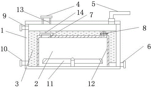
[0015] Example 1: Such as figure 1 A kind of anaerobic fermentation tank for sludge treatment is shown, the fermentation tank is a rectangular housing 1, the top of the housing 1 is provided with a feed port 4 and an exhaust port 5, the The side of the housing 1 is provided with a discharge port 6, the housing 1 is provided with a sealed rectangular fermenter 2, and a sealed heat transfer tank 3 is provided between the fermenter 2 and the housing 1. The bottom of the fermentation tank 2 is provided with an electric stirring paddle 11, and the top of the fermentation tank 2 is provided with a secondary feed port 7 and a waterproof and breathable valve 8, and the secondary feed port 7 is arranged at the feed port 4, the outlet 6 is fixedly connected to the bottom of the fermentation tank 2.

Embodiment 2

[0016] Example 2: Such as figure 1 As shown, the top of the liquid-sealed heat transfer tank 3 is provided with a reflux liquid inlet 9, and the bottom is provided with a reflux liquid outlet 10; through the reflux liquid inlet / outlet 9 and 10 on the liquid-sealed heat transfer tank 3, It is convenient to circulate the reflux liquid, and at the same time, the heated reflux liquid is used for other heat preservation equipment, which is convenient for the comprehensive utilization of energy.

Embodiment 3

[0017] Example 3: Such as figure 1 As shown, the feed port 4 is provided with a telescopic feed pipe 13, and the telescopic feed pipe 13 is fixedly connected to the feed port 4 and the secondary feed port 7 as a whole; through the telescopic feed pipe 13. It is convenient to connect the feed port 4 and the secondary feed pipe 7, and it is convenient to pass the sludge into the fermentation tank 2. The operation is simple and convenient, and the overall sealing performance of the device is good.


PUM


Abstract

The invention discloses an anaerobic fermentation tank for sludge treatment. The fermentation tank is a rectangular housing, wherein the housing is internally provided with a sealed rectangular fermenter; a sealed heat transmission groove is formed between the fermenter and the housing; an electric mixing propeller is arranged at the bottom of the fermenter; a secondary feed port and a water-proof breather valve are formed and arranged at the top of the fermenter; and the secondary feed port is formed under a feed port. According to the anaerobic fermentation tank, a sealing system of the original ordinary fermenter is improved; reflux liquid can ensure a higher sealing effect in the fermenter and is matched with the electric mixing propeller for slow mixing to ensure that heat generated by anaerobic fermentation in sludge is uniformly diffused into the reflux liquid; the normal fermentation temperature in the fermenter is ensured; and the working efficiency of the whole device is high.

Description

technical field [0001] The invention relates to the field of recovery and reuse of sludge, and in particular provides an anaerobic fermentation tank for treating sludge with microorganisms. Background technique [0002] With the development of the economy, the amount of sludge produced in production and life is increasing day by day, and the treatment of sludge has become one of the problems that must be solved in the economic development of modern cities and enterprises; The mud is stored in the sludge storage tank for anaerobic fermentation, and the flammable gas generated by anaerobic fermentation is used as the main energy source for the sludge drying after dehydration in the later stage. At the same time, anaerobic fermentation can kill most of the harmful substances in the sludge. Bacteria and viruses are convenient for the next step of sludge treatment. [0003] However, as a mixture of solid and liquid, sludge has the following problems in the anaerobic fermentation...

Claims


Application Information

Patent Timeline
Patent Type & Authority Patents(China)
IPC IPC(8): C02F11/04
CPCC02F11/04C02F2209/02C02F2303/06
Inventor 徐荣军
Owner TAIZHOU MING FENG TECH CO LTD RENEWABLE RESOURCES
Why Eureka
Try Eureka