Oil tank for hydraulic system
A hydraulic system and oil tank technology, applied in fluid pressure actuation system components, oil supply tank devices, fluid pressure actuation devices, etc., can solve problems such as poor heat dissipation, many bubbles, inconvenient maintenance and cleaning, etc., to achieve Increased flow area, easy maintenance, and easy cleaning of the filter
- Summary
- Abstract
- Description
- Claims
- Application Information
AI Technical Summary
Problems solved by technology
Method used
Image

Examples
Embodiment Construction
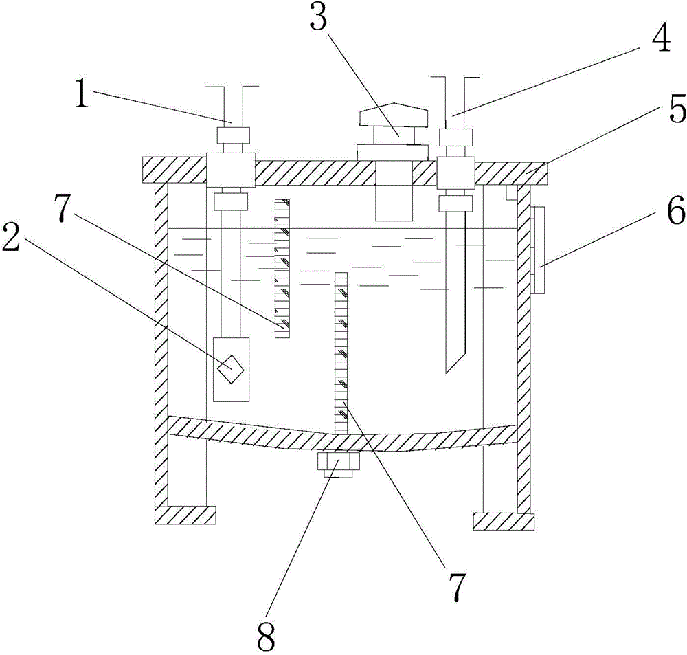
[0014] Such as figure 1 The shown oil tank for a hydraulic system includes a tank body and a tank cover 5, the left side of the tank body is provided with an oil suction pipe 1, and the oil suction tube 1 extends out of the tank body through a through hole on the tank cover 5 The outside of the box is sealed and fixed with the box body, and the right side of the box body is provided with an oil return pipe 4, and the oil return pipe 4 passes through the through hole on the box cover 5 and extends out of the box body, and is sealed and fixed with the box body, The bottom of the box is an arc-shaped surface, and a plurality of partitions 7 are arranged between the oil suction pipe 1 and the oil return pipe 4, and the partitions 7 are fixed on the inner wall of the box, and the bottom of the box is provided with An oil drain plug 8, the bottom of the oil suction pipe 1 is provided with an oil suction filter 2. An oil level indicator 6 is installed on the side wall of the casing....
PUM
 Abstract
Description
Claims
Application Information
PatSnap Eureka turns technology decisions into work you can execute. Powered by our Innovation Knowledge Graph, it runs expert workflows across engineering, life sciences, materials and intellectual property. Get your review-ready output in minutes.


