Inertial container device with continuously-adjustable inertia coefficient

A technology of inertia coefficient and inerter, which is applied in the direction of transmission, flywheel, belt/chain/gear, etc., can solve the problems of heavy weight, unchangeable inertia coefficient, and ineffective use of flywheel energy, etc., to achieve saving energy effect

Inactive Publication Date: 2015-03-11
JIANGSU UNIV
View PDF4 Cites 10 Cited by
  • Summary
  • Abstract
  • Description
  • Claims
  • Application Information

AI Technical Summary

Problems solved by technology

[0004] Because the rack and pinion inerter adopts a homogeneous flywheel, its own weight is relatively large, and its inertial coefficient cannot be changed once it is designed. There are not enough inerters with variable in

Method used


Image

  • Inertial container device with continuously-adjustable inertia coefficient

Examples


Embodiment Construction

[0019] The present invention will be further described below in conjunction with the accompanying drawings and specific embodiments, but the protection scope of the present invention is not limited thereto.

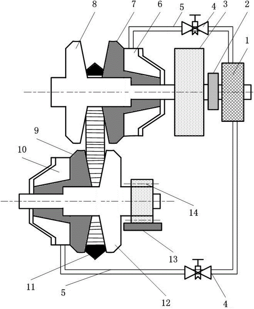
[0020] Such as figure 1 As shown, the inerter device with continuously adjustable inertia coefficient according to the present invention includes a driving wheel, a driven wheel, a gear 14, a rack 13, a flywheel 3, a hydraulic pump 1, a driving wheel hydraulic control cylinder 10, a driven wheel hydraulic Control cylinder 6. The driving wheel is composed of a driving wheel movable part 9 and a driving wheel fixed part 12 . The drive wheel fixing part 12 includes a drive shaft and a wheel integrally formed, and the gear 14 is mounted on the drive shaft and meshes with the rack 13 . The movable part 9 of the driving wheel is a wheel with a hole in the center, and the movable part 9 of the driving wheel can be axially moved and assembled on the driving shaft, and the movab...


PUM


Abstract

The invention provides an inertial container device with a continuously-adjustable inertia coefficient. The inertial container device comprises a driving wheel, a driven wheel, a gear, a rack/flywheel/hydraulic pump, a driving wheel hydraulic control cylinder and a driven wheel hydraulic control cylinder, wherein a V-shaped groove is formed between the movable part and the fixed part of the driving wheel; the gear is arranged on a driving shaft, and is meshed with the rack; a V-shaped groove is formed between the movable part and the fixed part of the driven wheel; the flywheel is arranged on a driven shaft; the driven wheel is driven by an elastic metal belt arranged in the two V-shaped grooves; the movable parts of the driving wheel and the driven wheel are driven by the driving wheel hydraulic control cylinder and the driven wheel hydraulic control cylinder which are connected with a hydraulic pump respectively. The engagement radius of the metal belt is adjusted through axial movement of the movable part of the driving wheel and the movable part of the driven wheel, so that the transmission ratio between the driving wheel and the driven wheel is adjusted, and continuous adjustment of the inertia coefficient is realized.

Description

technical field [0001] The invention relates to an inerter device with continuously adjustable inertia coefficient. Background technique [0002] SMITH, a scholar at the University of Cambridge, proposed the idea of ​​an inerter and designed a rack and pinion inerter and a ball screw inerter, realizing a strict correspondence between mechanical and electronic networks and promoting the development of mechanical networks. A suspension network is realized with three components of spring, damper and inertial container, which further improves the overall performance of the vehicle. [0003] Chinese patent 200810123830.8 discloses a rack and pinion inerter, which is a real two-terminal element like a spring and a damper. The rack and pinion inerter is composed of a box body, a flywheel, a pinion shaft A, a bull gear, a pinion shaft B and a rack. The rack is meshed with the pinion shaft B, the bull gear is coaxially connected with the pinion shaft B and meshed with the pinion sh...

Claims


Application Information

Patent Timeline
IPC IPC(8): F16F15/31F16H33/00
CPCF16F15/31F16H9/18F16H2009/163
Inventor 陈龙杨军张孝良沈钰杰蒋涛
Owner JIANGSU UNIV
Why Eureka
Try Eureka