Three-stage pressure reducer

A technology of pressure reducer and pressure reducing valve, which is applied to safety valves, engine components, balance valves, etc., can solve the problems of workpiece breakage / poor interface quality, large pressure change of pressure reducer, unstable low-pressure gas, etc. The effect of stable air pressure, reduced pressure drop and reasonable distribution

Active Publication Date: 2015-03-11
NINGBO LONGXING WELDING CUTTING TECH STOCK
View PDF6 Cites 3 Cited by
  • Summary
  • Abstract
  • Description
  • Claims
  • Application Information

AI Technical Summary

Problems solved by technology

[0004] The above-mentioned two-stage pressure reducer has only two stages of pressure reduction. In the actual use process, the number of pressure reduction stages is small. The quality of the break / interface of the workpiece during welding is not good, multi-level air pressure changes are set, and the structural layout is complicated

Method used


Image

  • Three-stage pressure reducer
  • Three-stage pressure reducer
  • Three-stage pressure reducer

Examples


Embodiment Construction

[0025] The following are specific embodiments of the present invention and in conjunction with the accompanying drawings, the technical solutions of the present invention are further described, but the present invention is not limited to these embodiments.

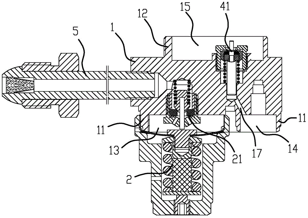
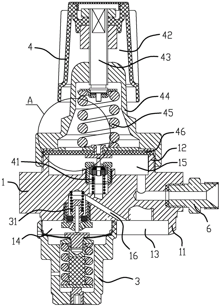
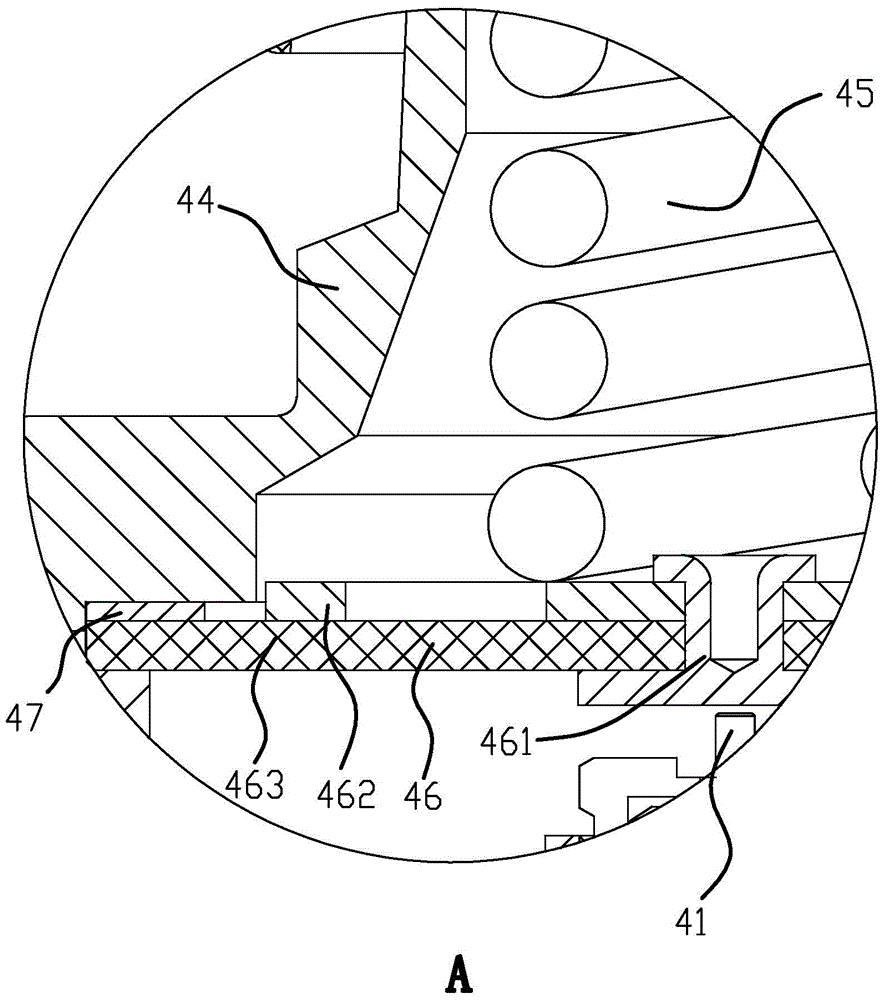
[0026] Such as Figure 1 to Figure 5 As shown, the three-stage pressure reducer includes a valve body 1, an inlet pipe 5 installed on the valve body 1, an outlet pipe 6, a high pressure gauge 81, a low pressure gauge 8, and a first-stage decompression valve installed on the valve body 1 respectively. Valve cover 2, secondary pressure reducing valve cover 3 and main pressure reducing valve cover 4, primary pressure reducing valve cover 2 and valve body 1 form a primary pressure reducing chamber 13, secondary pressure reducing valve cover 3 and valve body 1 forms a secondary decompression chamber 14, a main decompression chamber 15 is formed between the main decompression valve cover 4 and the valve body 1, a primary valve 2...


PUM


Abstract

The invention provides a three-stage pressure reducer, which belongs to the technical field of a pipeline and solves the problems that the pressure change of the existing pressure reducer is great, and the air pressure is unstable. The three-stage pressure reducer comprises a valve body, an air inlet pipe, an air outlet pipe, a primary pressure reducing valve cover and a main pressure reducing valve cover, wherein the air inlet pipe, the air outlet pipe, the primary pressure reducing valve cover and the main pressure reducing valve are arranged on the valve body, a primary pressure reducing chamber is formed between the primary pressure reducing valve cover and the valve body, a primary valve and a main valve are arranged on the valve body, the inside of the primary pressure reducing valve cover is tightly butted against the primary valve, the air inlet pipe and the primary pressure reducing chamber are communicated or closed through the primary valve, a main pressure reducing chamber is formed between the main pressure reducing valve cover and the valve body, the main pressure reducing chamber is connected with the air outlet pipe, the inside of the main pressure reducing valve cover is tightly butted against the main valve, a secondary valve and a secondary pressure reducing valve cover are also arranged on the valve body, a secondary pressure reducing chamber is formed between the secondary pressure reducing valve cover and the valve body, primary air passages communicated to the secondary valve are respectively arranged inside the primary pressure reducing chamber, and a secondary air passage communicated to the main valve is arranged on the secondary pressure reducing chamber. The three-stage pressure reducer has the advantages that the air pressure is stable, and the structure is exquisite and ingenious.

Description

technical field [0001] The invention belongs to the technical field of pipelines, and relates to a pressure reducer, in particular to a three-stage pressure reducer. Background technique [0002] The pressure reducing valve is a valve that reduces the inlet pressure to a certain required outlet pressure through adjustment, and relies on the energy of the medium itself to keep the outlet pressure automatically stable. Because the output in the gas cylinder is high-pressure gas, and the gas welding / cutting equipment needs stable low-pressure gas, the high-pressure gas is adjusted to low-pressure gas through the pressure reducer. [0003] Chinese patent CN201339816Y discloses a two-stage pressure reducer, including a valve body, an upper cover, a lower cover, a primary valve, and a secondary valve; the valve body is connected with the lower cover to form a primary decompression chamber, and the The valve body is connected with the upper cover to form a secondary decompression ...

Claims


Application Information

Patent Timeline
Patent Type & Authority Applications(China)
IPC IPC(8): F16K17/06
CPCF16K17/06
Inventor 邱龙龙蒋小琳
Owner NINGBO LONGXING WELDING CUTTING TECH STOCK
Why Eureka
Try Eureka