Catalytic combustor for a gas turbine

Inactive Publication Date: 2005-09-27
CATACEL
View PDF19 Cites 0 Cited by
  • Summary
  • Abstract
  • Description
  • Claims
  • Application Information

AI Technical Summary

Benefits of technology

[0014]The invention has the further object of providing a catalytic combustor in which the temperature in the combustor is limited, so as to prevent deactivation of the catalyst.
[0015]The invention has the further ob

Problems solved by technology

This uncoated band allows the structure to be welded, a

Method used


Image

  • Catalytic combustor for a gas turbine
  • Catalytic combustor for a gas turbine
  • Catalytic combustor for a gas turbine

Examples


Embodiment Construction

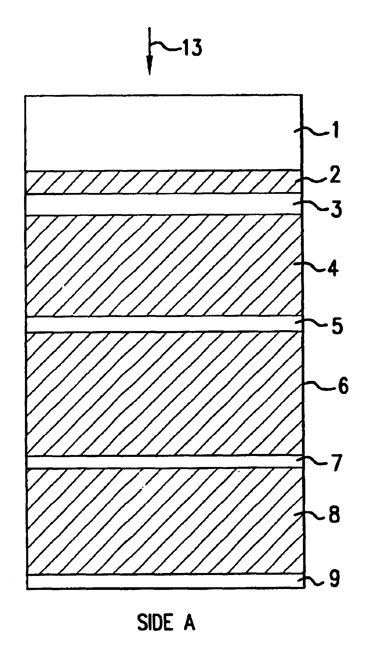
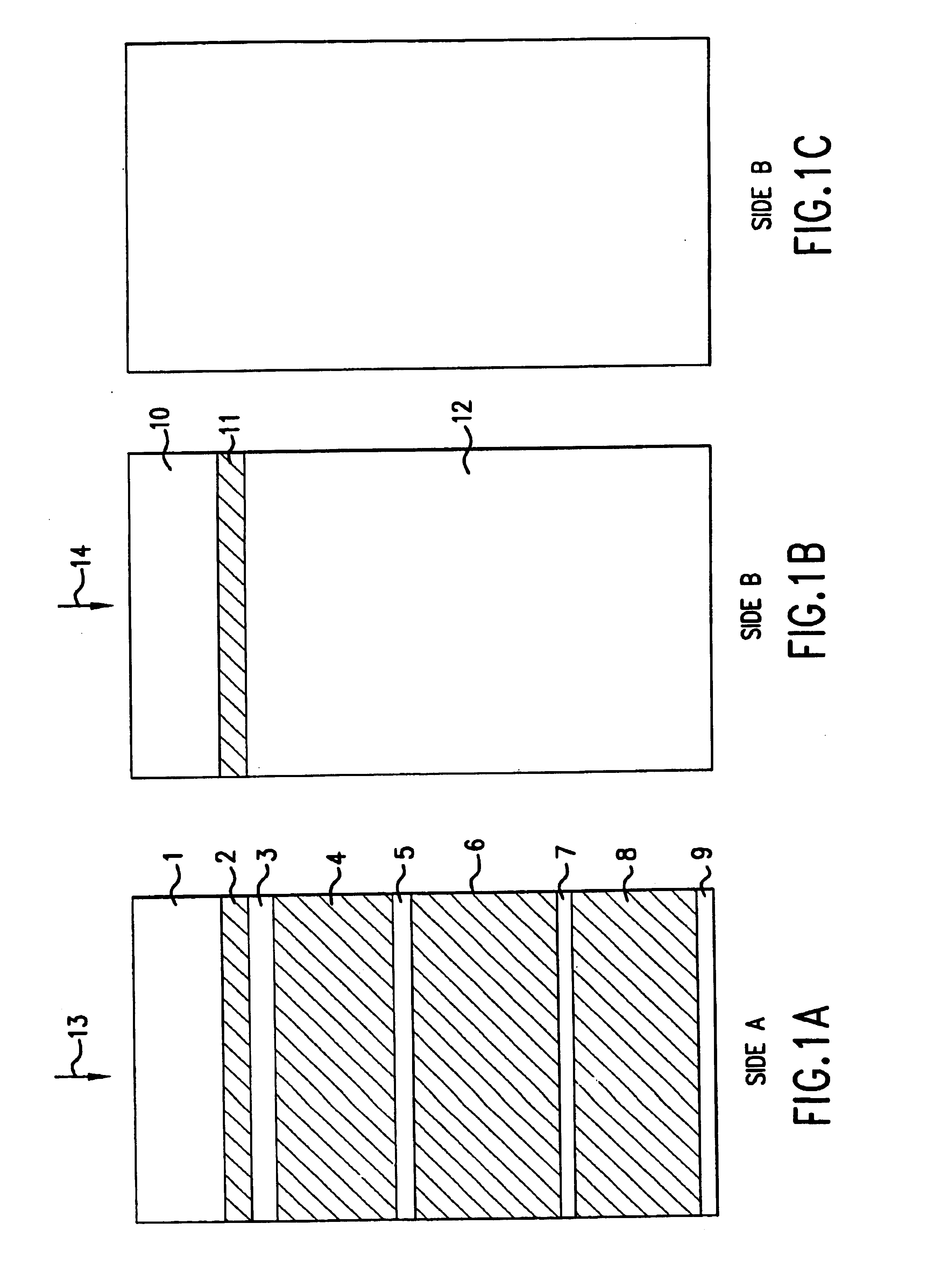
[0032]The present invention comprises a catalytic combustor formed of a plurality of strips coated with catalyst as shown in FIGS. 1A and 1B. FIG. 1A is a plan view of a first side of the strip, designated as Side A. FIG. 1B is a plan view of the other side of the same strip, designated as Side B. The strip has various bands, labeled 1 through 12, the cross-hatched areas representing those bands having a catalyst coating, and the areas without cross-hatching representing those bands having no catalyst coating.

[0033]The arrangement of FIGS. 1A and 1B applies whether the strip is flat or corrugated. For convenience of illustration, no corrugations are shown.

[0034]Band 1 is a wide, uncoated band, and band 10 is located on the opposite side of the strip from band 1. Bands 1 and 10 are located at the inlet end of the strip. That is, they are positioned at the end at which combustion gas flows into the combustor. Arrows 13 and 14, pertaining to Sides A and B, respectively, indicate the di...


PUM

PropertyMeasurementUnit
Widthaaaaaaaaaa
Widthaaaaaaaaaa
Widthaaaaaaaaaa

Abstract

A catalytic combustor for a gas turbine includes a stack of metal strips, each strip having an inlet end and an outlet end. The inlet ends of both sides of the strip are uncoated, to limit the temperature and maintain rigidity of the strip at the inlet end. In one embodiment, both sides of the strip have a light-off band, coated with catalyst, and adjacent to the uncoated inlet band. One side of the strip (Side A) also includes at least one combustion band, while the other side (Side B) has no corresponding coated band. The strips are arranged such that Side A of a given strip inside the stack faces Side A of an adjacent strip, and Side B of a strip inside the stack faces Side B of an adjacent strip. The resulting structure prevents overheating of the combustor, maintains its rigidity, and reduces the pressure drop through the combustor.

Description

BACKGROUND OF THE INVENTION[0001]This invention relates to a catalytic combustor for a gas turbine.[0002]The purpose of the catalytic combustor of the present invention, as opposed to a simple flame combustor, is to reduce the formation of nitrogen oxides, or NOx. This object is explained in U.S. Pat. No. 5,202,303, the disclosure of which is incorporated herein by reference.[0003]The catalytic combustor in the above-cited patent is a honeycomb comprised of metal strips which are coated with catalyst on just one side. The strips are stacked so that coated sides face each other and uncoated sides face each other. This stack of strips defines a structure in which catalyzed channels alternate with uncatalyzed channels. Only the portion of the fuel-air mixture which flows through the catalyzed channels is combusted within the honeycomb. Since the fuel-air mixture flowing through the uncatalyzed channels is not combusted, the honeycomb is cooled by that portion of the mixture, and the ca...

Claims


Application Information

Patent Timeline
IPC IPC(8): B01D53/88B01J37/02B01J35/00B01J35/04B01J37/00C01B3/04C01B3/00C01B13/02F01N3/28
CPCB01D53/885B01J35/04B01J37/0225C01B3/045C01B13/0207F01N3/281F01N2330/02F01N2330/40Y02E60/364Y02E60/36
Inventor CORNELISON, RICHARD C.RETALLICK, WILLIAM B.WHITTENBERGER, WILLIAM A.
Owner CATACEL
Why Eureka
Try Eureka