Pixel circuit, driving method thereof, display panel, display device
A pixel circuit and driving signal technology, applied in the field of organic light-emitting display, can solve problems such as uneven light emission of the display
- Summary
- Abstract
- Description
- Claims
- Application Information
AI Technical Summary
Problems solved by technology
Method used
Image

Examples
Embodiment 1
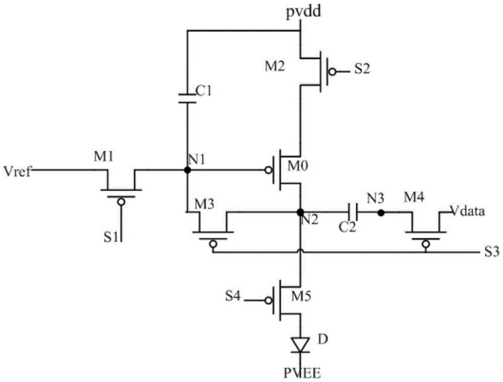
[0047] Based on this, the embodiment of the present application provides a pixel circuit, refer to image 3 As shown in , it is a schematic structural diagram of a pixel circuit provided in an embodiment of the present application, wherein the pixel circuit includes:
[0048] The first transistor M1, the second transistor M2, the third transistor M3, the fourth transistor M4 and the fifth transistor M5, the driving transistor M0, the first capacitor C1, the second capacitor C2 and the light emitting element D; wherein,
[0049] The driving transistor M0 is used to determine the magnitude of the driving current, and the magnitude of the driving current is determined by the voltage difference between the gate and the source of the driving transistor M0;
[0050] The first transistor M1 is controlled by the first driving signal S1, and is used to transmit the reference voltage signal Vref to the gate of the driving transistor M0;
[0051] The second transistor M2 is controlled b...
Embodiment 2
[0075] In addition, a preferred embodiment of the present invention also provides a display panel, including a pixel circuit, wherein the pixel circuit adopts the pixel circuit described in the above-mentioned embodiments.
[0076] Embodiment 2 The pixel circuit provided by the display panel may have a pure PMOS structure, or may have a CMOS structure in which the driving transistor is a Pmos transistor and other transistors are NMOS transistors. In the corresponding working process, the data signal input terminal needs to input a value equal to the reference voltage signal in the threshold grabbing step of the pixel circuit.
[0077] The pixel circuit in the display panel makes the driving current not only independent of the threshold voltage of the driving transistor itself, but also independent of the voltage drop of the power signal and the voltage across the two ends of the light-emitting element through the cooperation between each transistor and the capacitor, thus elimi...
Embodiment 3
[0080] The third preferred embodiment of the present invention provides a display device, the display device includes a display panel, wherein the display panel adopts the display panel as described in the second embodiment.
[0081] It should be noted that the "coupling" mentioned in the embodiments of the present invention refers to the electrical connection between two components, including direct electrical connection and indirect electrical connection.
PUM
 Abstract
Description
Claims
Application Information
 - R&D Engineer
- R&D Manager
- IP Professional
- Industry Leading Data Capabilities
- Powerful AI technology
- Patent DNA Extraction
Browse by: Latest US Patents, China's latest patents, Technical Efficacy Thesaurus, Application Domain, Technology Topic.
© 2024 PatSnap. All rights reserved.Legal|Privacy policy|Modern Slavery Act Transparency Statement|Sitemap