High-safety and short-stroke short circuit grounding device
A grounding device and safety technology, applied in the field of clutch rotating short-circuit grounding device, can solve the problems of easy falling off of the short-circuit grounding device, inconvenient operation, poor safety, etc., and achieve the effects of convenient torque design, low production cost and easy operation
- Summary
- Abstract
- Description
- Claims
- Application Information
AI Technical Summary
Problems solved by technology
Method used
Image
Examples
Embodiment 1)
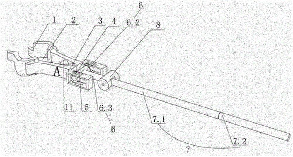
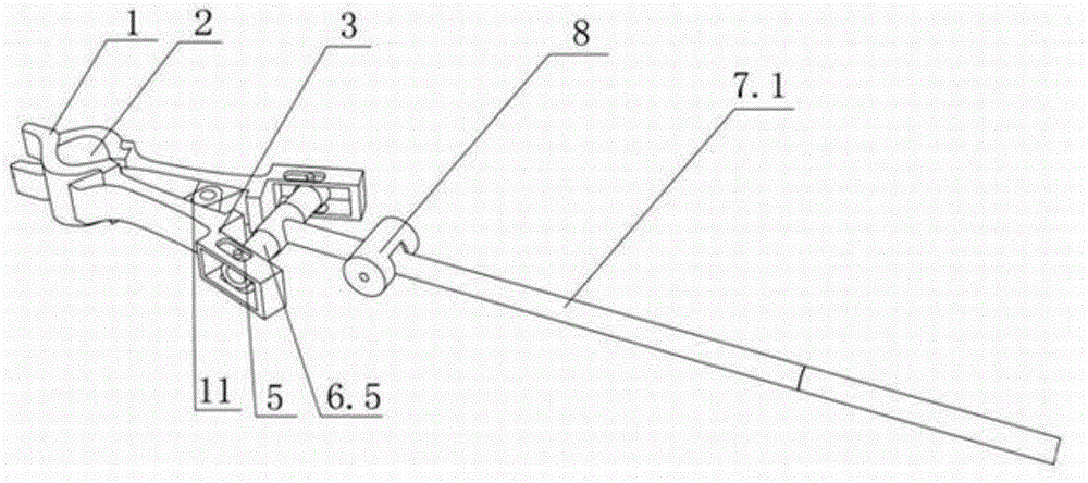
[0026] Such as Figure 2 to Figure 6As shown, the short-circuit grounding device with better safety and shorter stroke in this embodiment is a clutch rotating short-circuit grounding device, which includes a wire end clamp A and a handle 7 . The wire end clamp A includes a pair of splints 1 connected to the steering shaft by means of a support piece 11 and an arc-shaped bite 2 is provided on the upper part. A spring is wound around the rotating shaft 12 of the support piece 11 . Both ends of the spring are against the inner sidewalls of the two splints 1 . The pair module 3 is provided at the end of the wire terminal clamp A. A movable nut 4 is provided in the module 3 . The movable nut 4 is connected with the movable piece 5 arranged on the pair module 3 through a screw. The movable nut 4 can rotate laterally along the screw rod. Movable piece 5 can slide on module 3. The telescopic mechanism 6 includes a pair of telescopic rods 6.1, a cover cylinder 6.2, a guide cylind...
Embodiment 2)
[0030] Such as Figure 7 to Figure 8 As shown, the difference from Embodiment 1 is that: the inner side wall of the splint 1 is also provided with a depressing tongue 13 , and the depressing tongue 13 is arranged between the rotating shaft 12 and the arc-shaped bite 2 . The other splint 1 is correspondingly provided with a tongue-pressing through hole. The function of the depressing tongue 13 is: when the wire end clamp A is in the open state, the depressing tongue 13 is used to resist the wire end clamp A, so as to avoid the force of the spring to make the telescopic rod 6.1 move back. When it is necessary to loosen the splint 1 for clamping, the pressing tongue 13 contacts the wire, and the wire end clamp A can be released. The remaining technical principles are the same as in Embodiment 1.
Embodiment 3)
[0032] The difference from Embodiment 1 is that the telescopic rod 6.1, the rotating rod 6.4, and the grip rotating rod 7.3 are all threaded, and the rest of the operation methods are the same as in Embodiment 1.
PUM
 Abstract
Description
Claims
Application Information
 - R&D
- Intellectual Property
- Life Sciences
- Materials
- Tech Scout
- Unparalleled Data Quality
- Higher Quality Content
- 60% Fewer Hallucinations
Browse by: Latest US Patents, China's latest patents, Technical Efficacy Thesaurus, Application Domain, Technology Topic, Popular Technical Reports.
© 2025 PatSnap. All rights reserved.Legal|Privacy policy|Modern Slavery Act Transparency Statement|Sitemap|About US| Contact US: help@patsnap.com


