Steering device

一种转向装置、狭缝的技术,应用在转向控制、转向机构、运输和包装等方向,能够解决紧固性牺牲等问题,达到操作载荷抑制、滑动性良好、轻快操作性的效果

Active Publication Date: 2015-03-18
YAMADA SEISAKUSHO KK
View PDF7 Cites 0 Cited by
  • Summary
  • Abstract
  • Description
  • Claims
  • Application Information

AI Technical Summary

Problems solved by technology

[0008] Therefore, the holding force caused by the contact between the inner peripheral side of the hugging main body and the outer peripheral side of the inner pipe is different in the axial direction between the circumferential support portion side and the opposite side, and the fastening property may be slightly sacrificed. There is still room for improvement

Method used


Image

  • Steering device
  • Steering device
  • Steering device

Examples


Embodiment Construction

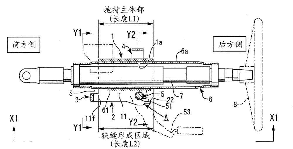
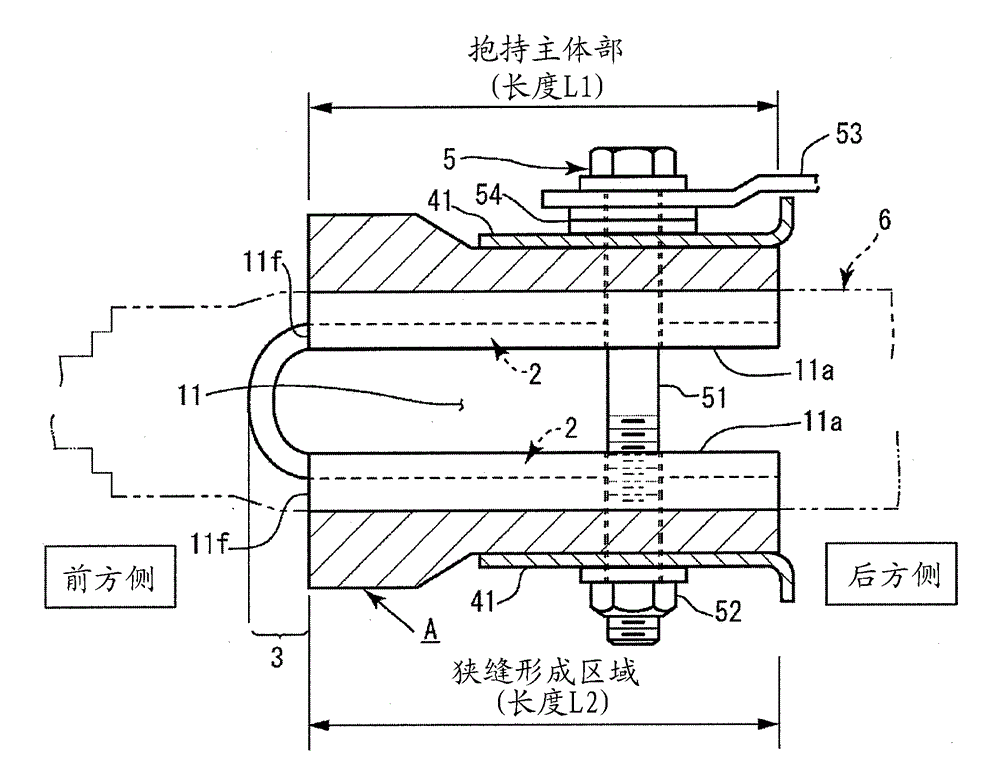
[0024] In the present invention, there are first and second embodiments, and the first embodiment will be described starting from the first embodiment. The main structure is shown in Figure 1 and Figure 2, which are the outer column A, the fixing bracket 4, the fastening tool 5 and the inner pipe 6.

[0025] Here, as words indicating directions in the present invention, there are front side and rear side. The front side and the rear side are based on the front-rear direction of the vehicle when the steering device is installed in the vehicle. Specifically, among the components of the steering device, the front wheel side of the automobile is defined as the front side, and the steering wheel (steering wheel) 8 side is defined as the rear side.

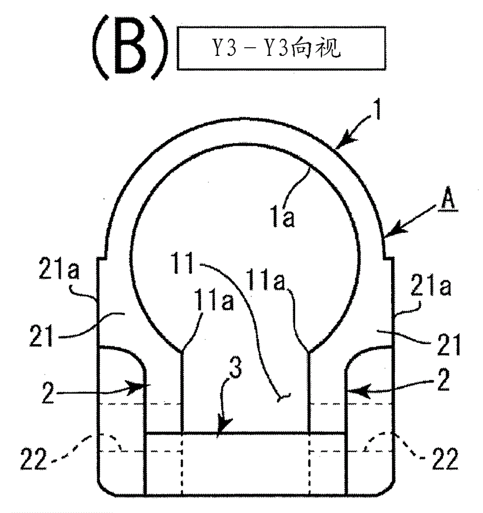
[0026] The outer column A is composed of a holding body part 1 , a fastening part 2 and a connecting part 3 . As shown in FIG. 3 , the above-mentioned holding body part 1 is formed in a substantially cylindrical shape with a hollow in...


PUM


Abstract

A steering device includes: a fixing bracket; an outer column A including a gripping main body portion which is installed swingably on the fixing bracket and which grips an inner pipe, a slit portion formed along the gripping main body portion, clamping portions formed along an axial direction of slit edges which are mutually opposing in the width direction of the slit portion, and a coupling portion which couples together the two clamping portions; and a clamping tool which expands and contracts an interval between the two coupling portions of the outer column A. The coupling portion projects to the outer side of a forming region of the slit portion.

Description

technical field [0001] The present invention relates to a steering device capable of reliably fastening and releasing an inner tube to which a steering shaft is attached, in a steering device having a tilt-telescopic adjustment function. Background technique [0002] Generally, a steering device of an automobile is provided with a tilt-telescopic adjustment mechanism. As one of the general configurations of such a steering device, a steering device already developed by the applicant exists as Patent Document 1. As shown in FIG. It consists of a fixed bracket installed on the side of the vehicle body, an inner tube that rotatably supports the steering shaft, an outer column that slidably supports the inner tube in the axial direction, and tightens the inner tube through the outer column. The structure of the solid fastening mechanism. [0003] In Patent Document 1, a slit-shaped separation portion is formed on the holding body portion of the outer column along the axial dir...

Claims


Application Information

Patent Timeline
Patent Type & Authority Applications(China)
IPC IPC(8): B62D1/187
CPCB62D1/185B62D1/187B62D1/184
Inventor 川上高广町田一成
Owner YAMADA SEISAKUSHO KK
Why Eureka
Try Eureka