Process for treating waste liquid from catalytic cracking flue gas desulfurization

A technology for desulfurization waste liquid and treatment process, which is applied in gaseous effluent wastewater treatment, oxidized water/sewage treatment, sludge treatment, etc. problems, to achieve the effect of stable filtrate water quality, complete solid-liquid separation, and small footprint

Inactive Publication Date: 2015-03-18
CHINA PETROLEUM & CHEM CORP +1
View PDF9 Cites 31 Cited by
  • Summary
  • Abstract
  • Description
  • Claims
  • Application Information

AI Technical Summary

Problems solved by technology

[0004] In order to solve the problems existing in the prior art such as large equipment occupation area, high operating cost, incomplete solid-liquid separation, high water content of mud cake, etc., the present invention provides a catalytic cracking flue gas desulfurization waste liquid treatment process, using the process equipment Small footprint, low operating cost, complete solid-liquid separation, clear liquid can be discharged directly; mud cake has low water content, can be directly transported, and has a good operating environment

Method used


Image

  • Process for treating waste liquid from catalytic cracking flue gas desulfurization
  • Process for treating waste liquid from catalytic cracking flue gas desulfurization
  • Process for treating waste liquid from catalytic cracking flue gas desulfurization

Examples


Embodiment Construction

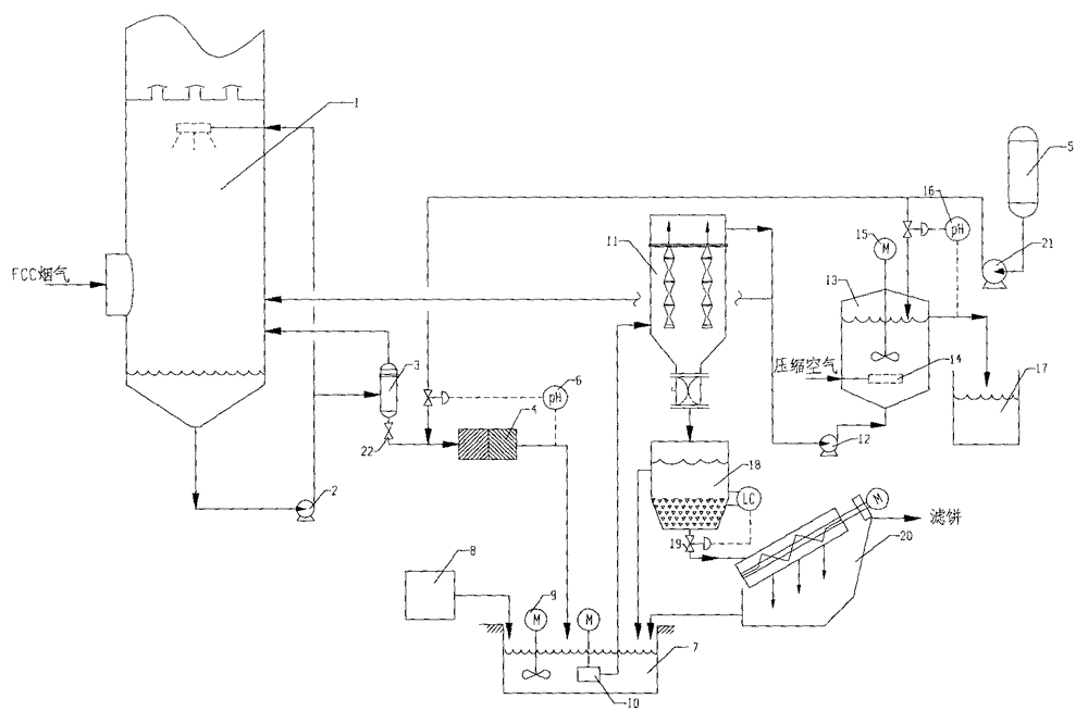
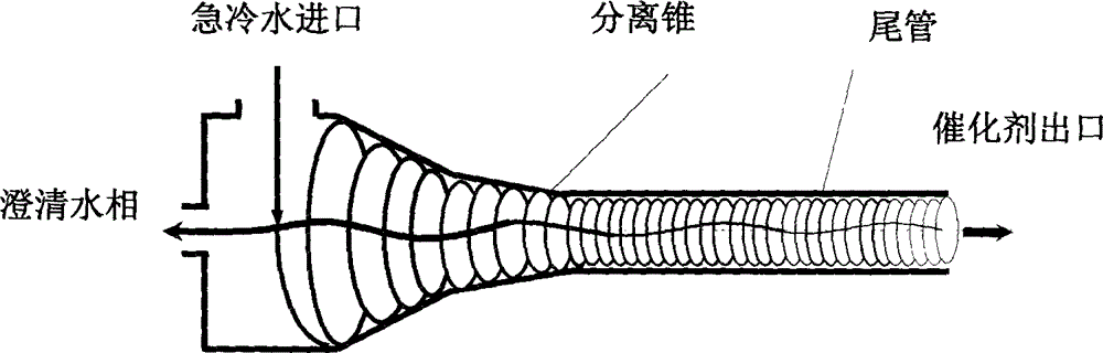
[0022] Below in conjunction with accompanying drawing, the present invention will be further described, as figure 1 As shown, the FCC flue gas enters the quenching scrubber 1 from the middle and lower part of the quenching scrubber 1 for quenching and saturation, forming an acidic waste liquid containing particulate matter, sulfate and sulfite. The waste liquid is discharged from the bottom of the tower, and most of it passes through the circulation pump. 2. Circulate back to the quenching washing tower 1, and the remaining part is sent to the hydrocyclone 3 for concentrated solid-liquid separation, and the catalyst dust is separated from the waste liquid, and the thin liquid produced by separation returns to the quenching washing at the top of the hydrocyclone 3 The tower 1 is circulated, and the concentrated liquid containing more particles produced by separation enters the neutralization reactor 4 through the bottom of the hydrocyclone 3 .

[0023] The concentrated liquid c...


PUM


Abstract

The invention provides a process for treating waste liquids from catalytic cracking flue gas desulfurization. The process comprises the following steps: enabling a part of waste liquids from a quenching washing tower to enter a hydraulic cyclone separator so as to be subjected to solid-liquid separation, returning the thin liquids to the quenching washing tower so as to be recycled, enabling the thick liquids to enter a neutralization reactor so as to be subjected to neutralization reaction, enabling the neutralized waste liquids to enter a slurry pond so as to be mixed with a flocculating agent uniformly, and enabling the mixture to enter an expansion-drum type filter so as to be subjected to solid-liquid separation with a thick slurry and a supernatant being obtained; returning part of the supernatant to the quenching washing tower so as to be recycled, discharging the remaining supernatant into an oxidation tank, removing the pseudo-COD containing sulfite roots and bisulfite roots by oxidizing, and directly discharging the qualified sewage; enabling the thick slurry to enter a settling pond from the bottom of the expansion-drum type filter so as to be further settled, feeding the thick slurry subjected to settlement into a dewatering machine so as to be concentrated and dewatered, directly transporting the filter cakes obtained by dewatering the thick slurry, returning the filtrate from the dewatering of the thick slurry to the slurry pond, and mixing the filtrate with the waste liquids so as to be retreated. The process provided by the invention has the advantages of a stable and efficient treatment effect, strong shock resistance, low investment and small floor area occupation and convenience of operation.

Description

technical field [0001] The invention relates to a method for treating waste liquid, in particular to a process for treating waste liquid from catalytic cracking flue gas desulfurization. Background technique [0002] At present, wet flue gas desulfurization process is generally adopted for catalytic cracking flue gas, and wet flue gas desulfurization process includes two types: one-time absorption process and renewable absorption process. The regenerative absorption process converts the pollutants in the flue gas into highly pure SO 2 It is recycled, and it is paid attention to because it basically does not produce secondary pollution. It includes flue gas quenching and washing, SO 2 Operating units such as absorption and regeneration. Fresh water is used for flue gas quenching and washing to remove dust and cool down. During the normal operation of the system, it is necessary to control the content of suspended solids, chloride ions, and dissolved solids in the circulatin...

Claims


Application Information

Patent Timeline
Patent Type & Authority Applications(China)
IPC IPC(8): C02F9/04
CPCC02F9/00C02F1/38C02F1/44C02F1/52C02F1/66C02F1/72C02F11/121C02F2103/18
Inventor 裴旭东陈卫红郭荣群涂先红李朝恒王秀珍张凡郭玉涛
Owner CHINA PETROLEUM & CHEM CORP
Why Eureka
Try Eureka