Venting device and method for venting a fluid guide line

A technology of fluid guidance and exhaust device, which is applied to the direction of valves for ventilation, cocks including cut-off devices, valve devices, etc., which can solve the problems of high cost and achieve the effect of cost reduction

Inactive Publication Date: 2019-05-28
SCHAEFFLER TECH AG & CO KG
View PDF8 Cites 0 Cited by
  • Summary
  • Abstract
  • Description
  • Claims
  • Application Information

AI Technical Summary

Problems solved by technology

[0003] Such an exhaust device consists of a large number of parts, which must be well coordinated with one another, so that the manufacture of such an exhaust device entails high costs

Method used


Image

  • Venting device and method for venting a fluid guide line
  • Venting device and method for venting a fluid guide line
  • Venting device and method for venting a fluid guide line

Examples


Embodiment Construction

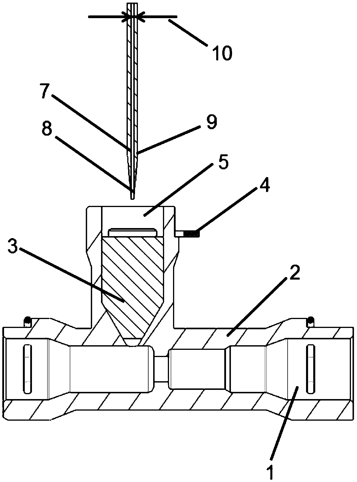
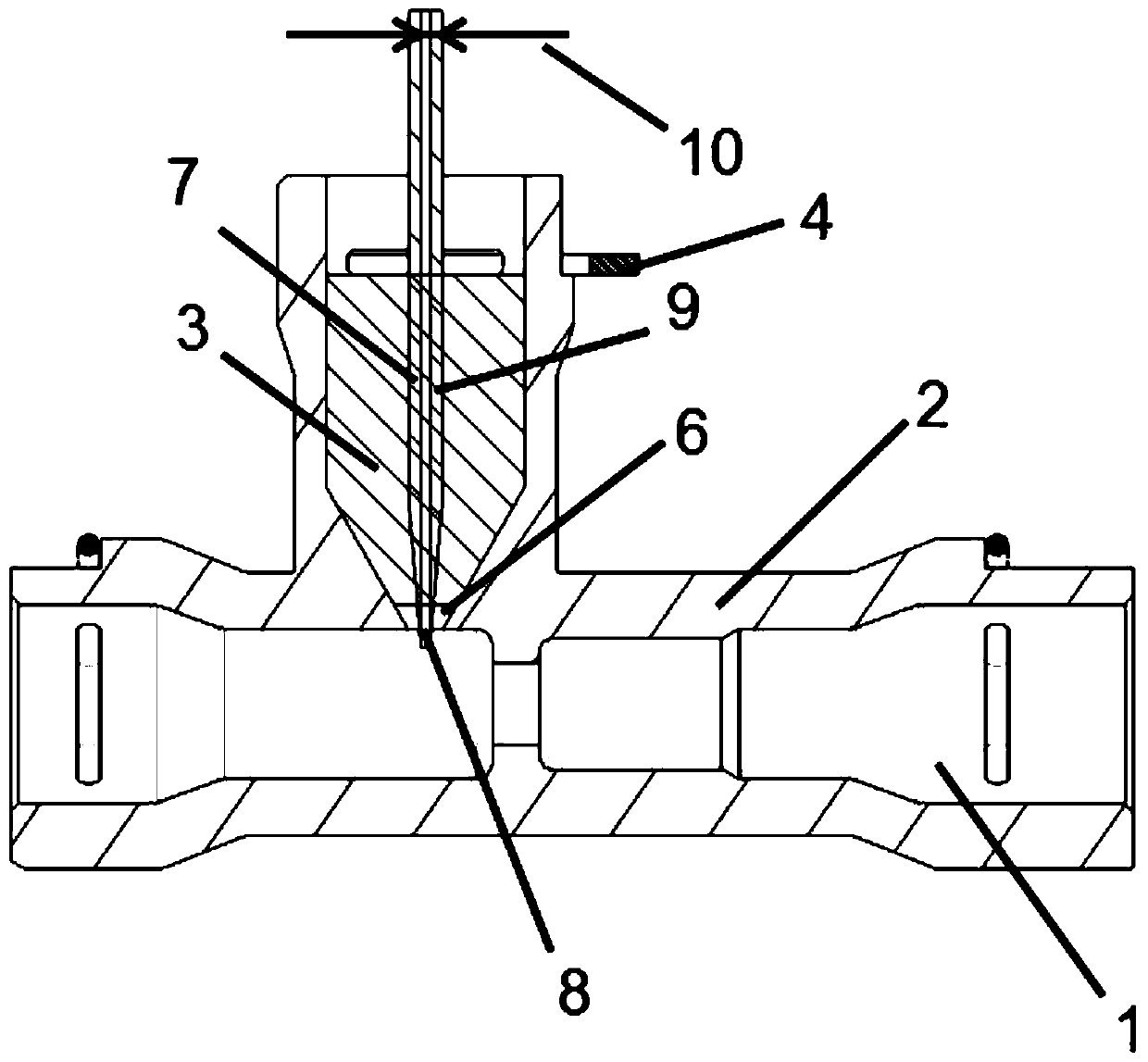
[0022] exist figure 1 shows a line 1 which is used in a hydraulic clutch actuation system of a motor vehicle and through which hydraulic fluid flows. An adapter housing 2 is introduced into the line 1 , which extends perpendicularly to the longitudinal extent of the line 1 . The adapter housing 2 is closed by a rubber seal 3 which completely fills the interior 5 of the adapter housing 2 . In this case, the sealing device 3 is pressed into the adapter housing 2 and held in place by a holder 4 which is placed over the sealing device 3 . The holder 4 is fastened to the adapter housing 2 and penetrates the adapter housing 2 from the outside into the interior 5 of the adapter housing 2 and is positioned there on the seal 3 . The inner space 5 of the adapter housing 2 has a funnel-like shape in the region directly opposite the line 1 . The pressed-in seal 3 is here adapted to the shape of the adapter housing 2 . However, a small cavity 6 remains between the tip of the funnel-li...


PUM


Abstract

The invention relates to an exhaust gear for exhausting a liquid guide pipeline of a hydraulic clutch operating system of a motor vehicle. The exhaust gear comprises an adapter shell, wherein an exhaust unit is arranged in the adapter shell. The exhaust unit is formed by a sealing device in the exhaust gear, which can be produced at low cost and can still work reliably, and an exhaust element penetrates through the sealing device.

Description

technical field [0001] The invention relates to a venting device for venting a fluid-conducting line of a hydraulic clutch actuating system of a motor vehicle, comprising an adapter housing in which a venting unit is inserted, the invention also relates to It relates to a method for venting a fluid conducting line. Background technique [0002] Numerous exhaust devices are already known which are arranged in fluid-conducting lines in order to expel air formed in the lines from the lines. In motor vehicles, especially in automatic hydraulic clutch systems such as image 3 and 4 Exhaust shown. exist image 3 A line 1 is shown in , which has an adapter housing 2 which extends perpendicularly to the direction of extent of the line 1 . The adapter housing 2 has an opening into which a vent valve 11 is inserted. The vent valve 11 is held here by a clamping band 12 which is fastened to the adapter housing 2 . The clamping band 12 is pre-tensioned in such a way that the vent va...

Claims


Application Information

Patent Timeline
Patent Type & Authority Patents(China)
IPC IPC(8): F16D25/12F16K13/00
CPCF16K24/04F16K5/0414F16L55/07
Inventor 高志川
Owner SCHAEFFLER TECH AG & CO KG
Why Eureka
Try Eureka