release mechanism

A technology of connecting plates and cutting cables, which is applied in the directions of weapon accessories, offensive equipment, weapon testing, etc., can solve the problems of high cost and poor safety, and achieve the effects of low cost, high safety, and convenient installation and use

Active Publication Date: 2016-06-22
HARBIN JIANCHENG GRP
View PDF5 Cites 0 Cited by
  • Summary
  • Abstract
  • Description
  • Claims
  • Application Information

AI Technical Summary

Problems solved by technology

[0003] The purpose of the present invention is to provide a release mechanism to solve the problems of poor safety and high cost of the existing release mechanism

Method used


Image

  • release mechanism
  • release mechanism
  • release mechanism

Examples


specific Embodiment approach 1

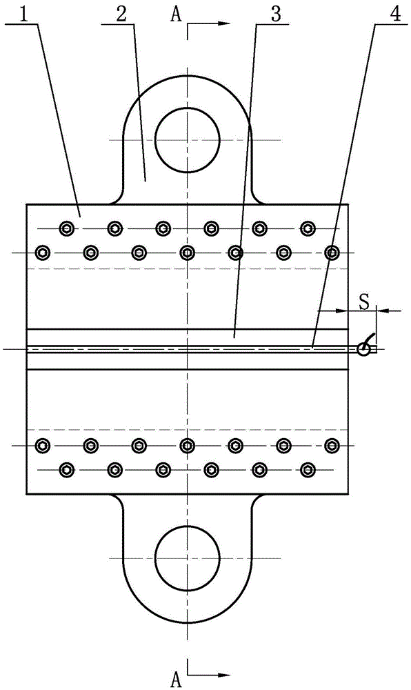
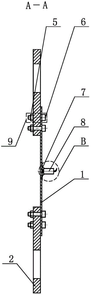
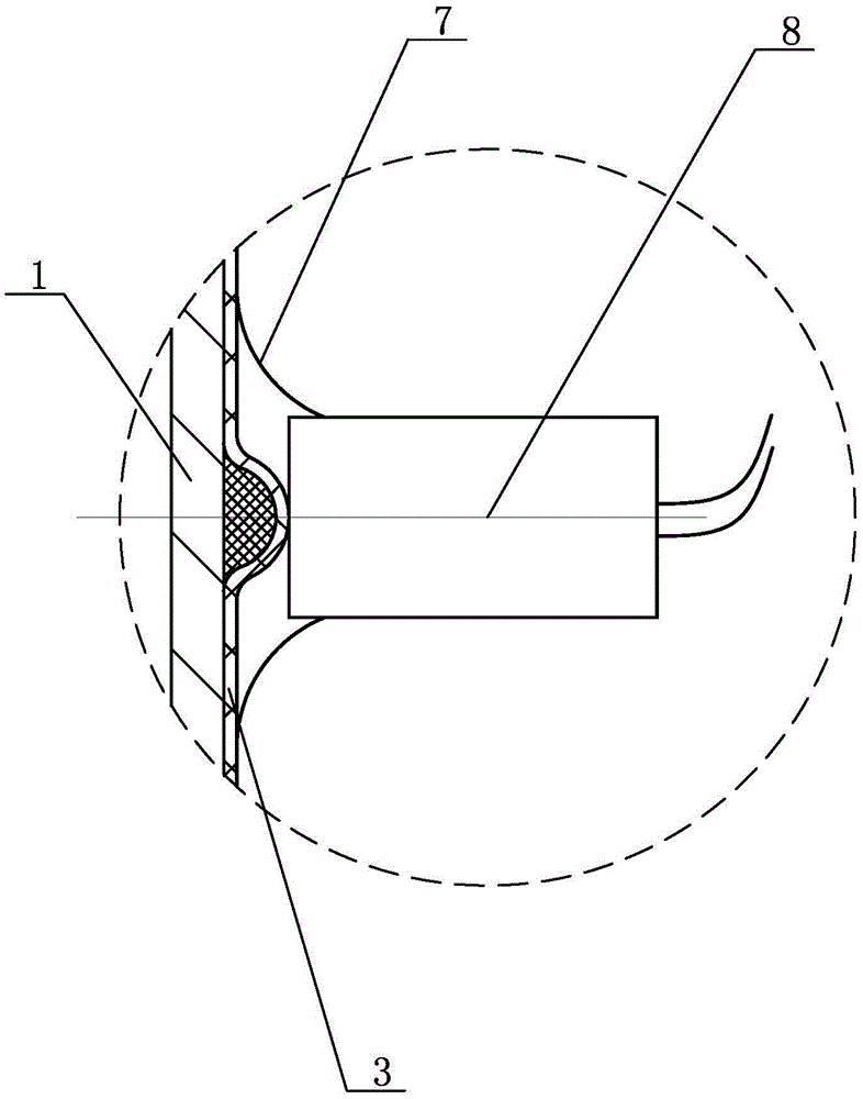
[0008] Specific implementation mode one: combine Figure 1 ~ Figure 3 Explain, the release mechanism of this embodiment, the release mechanism includes a connecting plate 1, an aluminum foil tape 3, a cutting cable 4, an insulating tape 7, a detonator 8, two connecting rings 2 and a plurality of screw fasteners 9; the connecting plate 1 Vertically arranged, the two connecting rings 2 and the connecting plate 1 are respectively fastened and connected by a plurality of screw fasteners 9, the center line of the two connecting rings 2 coincides with the vertical center line of the connecting plate 1, and the two connecting rings 2 coincide with the vertical center line of the connecting plate 1. The lifting ring 2 is arranged symmetrically with respect to the transverse centerline of the connecting plate 1, the V-shaped groove of the cutting cable 4 covers the entire horizontal centerline of one side panel of the connecting plate 1, and the detonating end of the cutting cable 4 is ...

specific Embodiment approach 2

[0009] Specific implementation mode two: combination figure 1 and figure 2 It is explained that each connection suspension ring 2 in this embodiment is fastened and connected with the connection plate 1 through 2 to 13 screw fasteners 9 . The undisclosed technical features in this embodiment are the same as those in the first embodiment.

specific Embodiment approach 3

[0010] Specific implementation mode three: combination figure 1 It is explained that 2 to 13 screw fasteners 9 in this embodiment are evenly distributed and fastened on the board surface where the connecting ring 2 and the connecting plate 1 are connected. The overall connection is reliable and stable. The undisclosed technical features in this embodiment are the same as those in the second embodiment.


PUM


Abstract

The invention relates to release mechanisms, particularly to a universal type release mechanism. The universal type release mechanism solves the problem that existing release mechanisms are poor in safety and high in cost. According to the universal type release mechanism, a connecting plate is vertically arranged, two connecting rings are connected with the connecting plate in a fastened mode through a plurality of screw fasteners, and the central line of the two connecting rings coincides with the vertical central line of the connecting plate; the two connecting rings are symmetric to each other relative to the horizontal central line of the connecting plate; the V-groove of cutting explosives covers the entire horizontal central line of one side of the connecting plate, the initiating end of the cutting explosives is arranged outside the connecting plate and spaced from the neighboring side wall of the connecting plate at a distance of S; the cutting explosives are attached to the connecting plate through aluminum foil adhesive tapes; a detonator is adhered to the cutting explosives through insulating tapes and arranged between the initiating end of the cutting explosives and the neighboring side wall of the connecting plate, and the output end of the detonator is aligned to the upper surface of the cutting explosives. The universal type release mechanism can be applied to drop test of weaponry as wells as other mechanisms requiring a quick cutting function.

Description

technical field [0001] The present invention relates to a release mechanism. Background technique [0002] At present, countries all over the world have stricter and stricter requirements on the safety of weapons and equipment, and more and more attention has been paid to them. It involves the safety of products during loading, unloading and transportation and the safety of product operators. The drop test is a must-do test for safety assessment. According to different product categories, there are drop test subjects at heights of 1.5m, 2m, 3m and 12m. On the steel plate of the 610mm thick concrete base, the safety of the product after an accidental drop is assessed. A release mechanism is required during the test, which must reliably bear the weight of the product and be cut off quickly during the test so that the product can fall freely without interference. There is no clear requirement for the release mechanism, and the specific implementation process and test methods...

Claims


Application Information

Patent Timeline
Patent Type & Authority Patents(China)
IPC IPC(8): F41A31/00
Inventor 权亚旭韩庆丽张玉亮戴军王立国
Owner HARBIN JIANCHENG GRP
Why Eureka
Try Eureka