Light source unit and projector

一种光源装置、荧光的技术,应用在光源、放映装置、点状光源等方向,能够解决彩色失衡等问题

Active Publication Date: 2015-03-18
CASIO COMPUTER CO LTD
View PDF12 Cites 34 Cited by
  • Summary
  • Abstract
  • Description
  • Claims
  • Application Information

AI Technical Summary

Problems solved by technology

If such a blue light source is used for the blue light source described in Patent Document 1, color imbalance will result.

Method used


Image

  • Light source unit and projector
  • Light source unit and projector
  • Light source unit and projector

Examples


no. 1 approach 〕

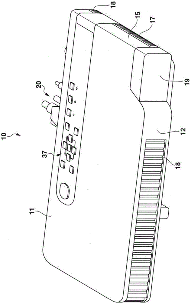
[0023] Hereinafter, the first embodiment will be described in detail based on the drawings. figure 1 It is an external perspective view of the projection device 10 . Here, in the first embodiment, left and right represent the left and right directions relative to the projection direction, and front and rear represent the front and rear directions relative to the screen side direction of the projection device 10 and the traveling direction of the light beam.

[0024] The projection device 10 according to the first embodiment is figure 1 As shown, it has a substantially rectangular parallelepiped shape, and has a lens cover 19 covering the projection opening on the side of the front panel 12 as the front side plate of the main body casing, and a plurality of air intake holes 18 are formed in the front panel 12 . In addition, although not shown, an Ir receiving unit for receiving a control signal from a remote controller is mounted on the front panel 12 .

[0025] In addition, ...

no. 2 approach 〕

[0087] Hereinafter, a second embodiment will be described with reference to the drawings. Parts corresponding to each other between the second embodiment and the first embodiment are given the same reference numerals. However, various limitations technically preferable for carrying out the present invention are given to the embodiments described below, but the scope of the present invention is not limited to the following embodiments and illustrated examples.

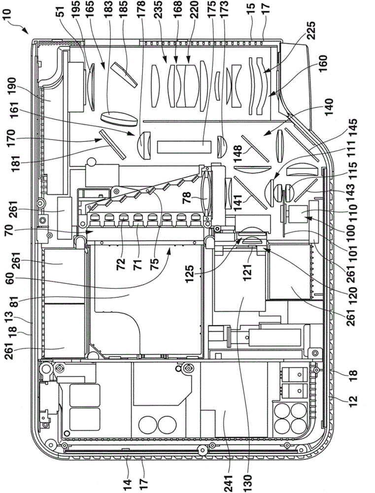
[0088] Figure 7 is a plan view of the projection device 10 .

[0089] The difference from the first embodiment lies in the configuration of the optical plate 101 (see Figure 8 ), between the lens and the second reflector 145 with the aspect of the band additional filter 90 (refer to Figure 7 ).

[0090] Figure 8 is a plan view of the optical plate 101 . Observed Figure 8 direction and observation Figure 7 The direction is vertical. Such as Figure 8 As shown, the optical plate 101 is divided into two seg...


PUM


Abstract

A light source unit includes a solid light emitting element that emits light in the blue wavelength range, a luminous light emitting portion on which a luminescent material layer is laid out, the luminescent material layer using the light emitted from the solid light emitting element as excitation light to emit light in a wavelength range of which wavelengths are longer than a wavelength of the excitation light, and a light transmitting portion that transmits the light emitted from the solid light emitting element, and an area of a luminescent material that emits luminous light in the green wavelength range is provided at part of the light transmitting portion.

Description

[0001] All disclosures including Japanese Patent Application No. 2013-177538 filed on August 29, 2013 and Japanese Patent Application No. 2013-184942 filed on September 6, 2013 including the specification, claims, drawings and abstract are hereby cited into this application. technical field [0002] The present invention relates to a light source device and a projection device in which a part of components on an optical path of blue-wavelength light has a phosphor region that emits fluorescent light in the green-waveband. Background technique [0003] Japanese Patent Application Laid-Open No. 2011-175000 discloses a method of sequentially irradiating multiple colors of light (red, green, blue, and white) to a display element, and then modulated by the display element according to time. A projection device of the field sequential method (time-division method) that generates color images by light synthesis. [0004] Japanese Patent Application Laid-Open No. 2002-90883 disclos...

Claims


Application Information

Patent Timeline
Patent Type & Authority Applications(China)
IPC IPC(8): G03B21/20F21V9/40
CPCF21Y2101/025G03B21/204F21V9/10F21Y2101/02F21K9/56G03B33/06
Inventor 小川昌宏
Owner CASIO COMPUTER CO LTD
Why Eureka
Try Eureka