Light source unit including an area of luminescent material emitting luminescent light in green wavelength range on part of member situated on optical path of light in blue wavelength range and projector

a technology of luminescent material and light source, which is applied in the field of light source units, can solve the problems that blue light from a blue light source does not form ideal blue ligh

Active Publication Date: 2017-01-10
CASIO COMPUTER CO LTD
View PDF10 Cites 19 Cited by
  • Summary
  • Abstract
  • Description
  • Claims
  • Application Information

AI Technical Summary

Benefits of technology

[0010]According to the invention, even though the blue light that is emitted by the blue light source looks purplish blue, since the light in the wavelength range of which the wavelengths are longer than the wavelength of the blue light is combined with the blue light, the light that passes through the wavelength range adding filter is corrected to be close to the ideal blue.
[0011]According to an aspect of the invention, there is provided a light source unit including a solid light emitting element that emits light in the blue wavelength range, a luminous light emitting portion on which a luminescent material layer is laid out, the luminescent material layer using the light emitted from the solid light emitting element as excitation light to emit light in a wavelength range of which wavelengths are longer than a wavelength of the excitation light, and a light transmitting portion that transmits the light emitted from the solid light emitting element, wherein an area of a luminescent material that emits luminous light in the green wavelength range is provided at part of the light transmitting portion.

Problems solved by technology

Incidentally, it happens occasionally that blue light from a blue light source does not form ideal blue light.

Method used


Image

  • Light source unit including an area of luminescent material emitting luminescent light in green wavelength range on part of member situated on optical path of light in blue wavelength range and projector
  • Light source unit including an area of luminescent material emitting luminescent light in green wavelength range on part of member situated on optical path of light in blue wavelength range and projector
  • Light source unit including an area of luminescent material emitting luminescent light in green wavelength range on part of member situated on optical path of light in blue wavelength range and projector

Examples


first embodiment

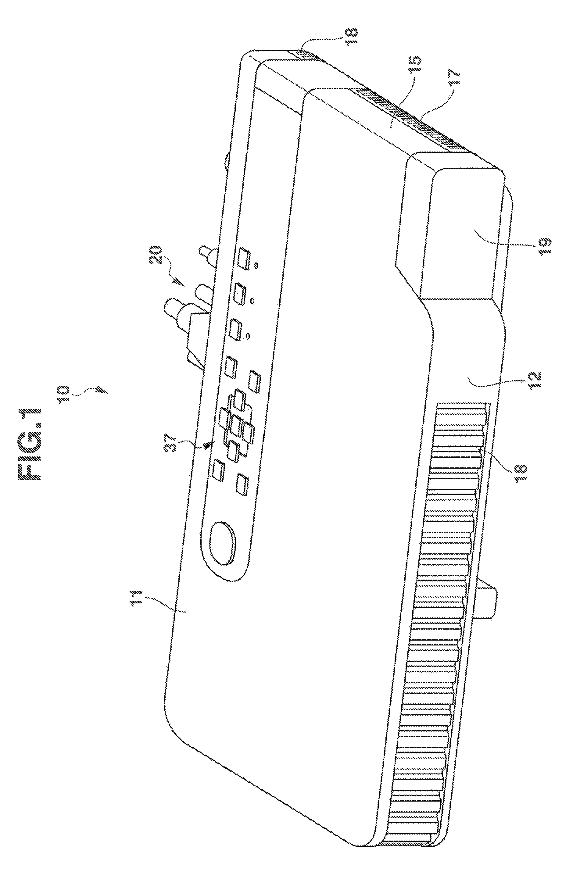
[0024]Hereinafter, a first embodiment will be described in detail based on the drawings. FIG. 1 is an external perspective view of a projector 10. In this embodiment, when referred to in relation to the projector 10, left and right denote, respectively, left and right in relation to the projecting direction of the projector 10, and when referred to in relation to the projector 10, front and rear denote, respectively, front and rear in relation to the direction of a screen and a traveling direction of a pencil of light that is emitted from the projector 10 towards the screen.

[0025]As shown in FIG. 1, the projector 10 according to the first embodiment has a substantially rectangular parallelepiped shape. The projector 10 has a lens cover 19 which covers a projection port which is disposed to a side of a front panel 12 which is referred to as a front side panel of a main body casing of the projector 10. Additionally, a plurality of outside air inlet slits 18 are provided in the front p...

second embodiment

[0088]Hereinafter, a second embodiment will be described by the use of the accompanying drawings. Like reference numerals are given to constituent elements of the second embodiment that correspond to those of the first embodiment. Although the following embodiment has various preferred technical limitations for carrying out the invention, those technical limitations are not intended to limit the scope of the invention to the embodiment and an illustrated example.

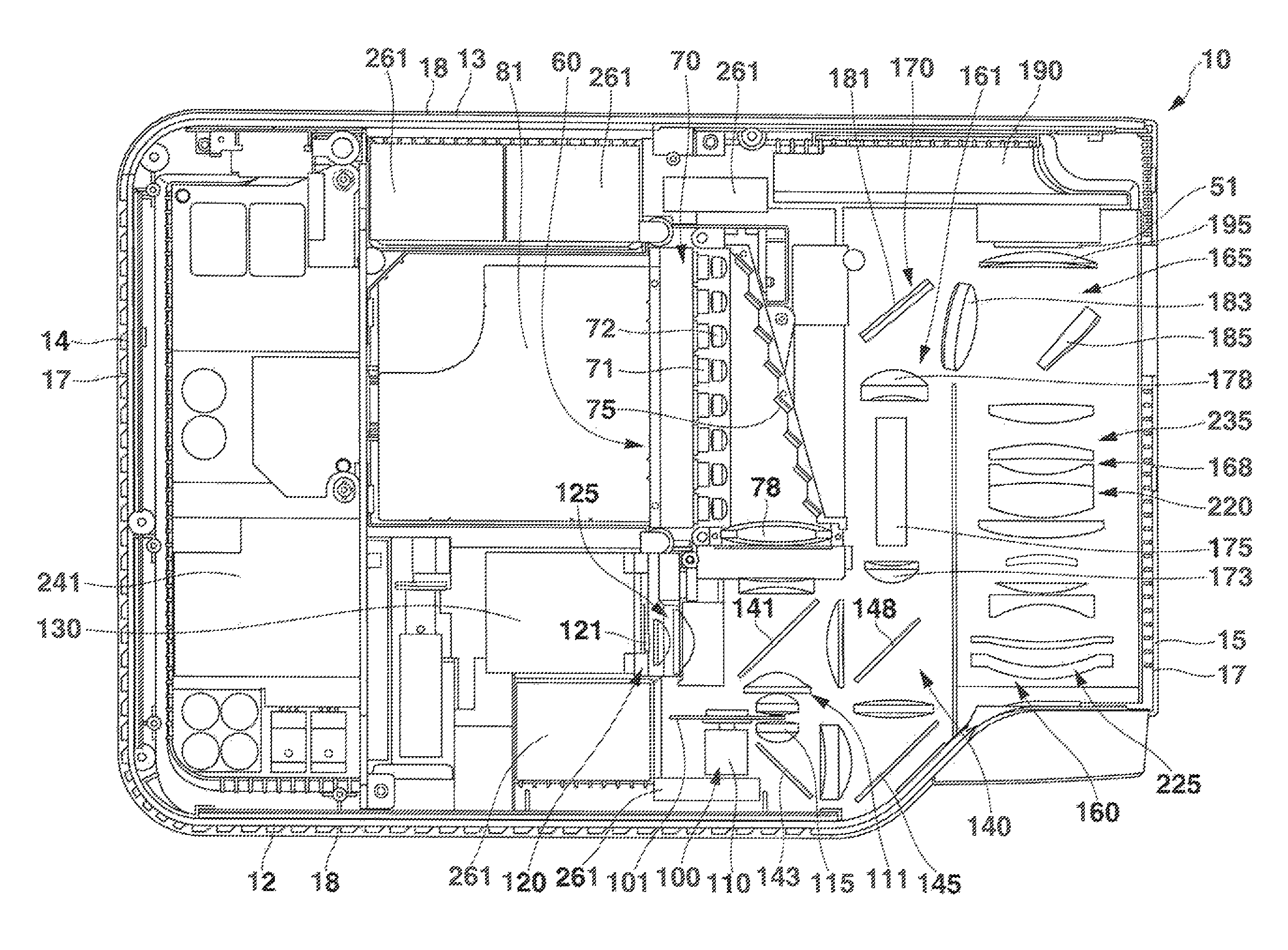
[0089]FIG. 7 is a plan view of a projector 10.

[0090]The second embodiment differs from the first embodiment in the configuration of an optical plate 101 (refer to FIG. 8) and in that a wavelength range adding filter 90 is provided between a lens and a second reflecting mirror 145 (refer to FIG. 7).

[0091]FIG. 8 is a plan view of the optical plate 101. A direction in which the optical plate 101 is seen in FIG. 8 is perpendicular to a direction in which the optical plate 101 is seen in FIG. 7. As shown in FIG. 8, the optical pl...


PUM


Abstract

A light source unit includes a solid light emitting element that emits light in the blue wavelength range, a luminous light emitting portion on which a luminescent material layer is laid out, the luminescent material layer using the light emitted from the solid light emitting element as excitation light to emit light in a wavelength range of which wavelengths are longer than a wavelength of the excitation light, and a light transmitting portion that transmits the light emitted from the solid light emitting element, and an area of a luminescent material that emits luminous light in the green wavelength range is provided at part of the light transmitting portion.

Description

CROSS-REFERENCE TO RELATED APPLICATION[0001]This application is based upon and claims the benefit of priority under 35 USC 119 from Japanese Patent Application No. 2013-177538 filed on Aug. 29, 2013, and Japanese Patent Application No. 2013-184942 filed on Sep. 6, 2013, the entire disclosures of which, including the descriptions, claims, drawings and abstracts, are incorporated herein by reference.BACKGROUND OF THE INVENTION[0002]Field of the Invention[0003]The present invention relates to a light source unit including an area of a luminescent material that emits luminescent light in the green wavelength range on part of a member that is situated on an optical path of light in the blue wavelength range, and a projector.[0004]Description of the Related Art[0005]Japanese Unexamined Patent Publication No. 2011-175000 (JP-2011-175000 A) discloses a projector utilizing a field sequential system (a time-division system) in which beams of light of a plurality colors (red, green, blue, whit...

Claims


Application Information

Patent Timeline
Patent Type & Authority Patents(United States)
IPC IPC(8): F21K99/00F21V9/10G03B21/20G03B33/06F21V9/40
CPCG03B21/204G03B33/06
Inventor OGAWA, MASAHIRO
Owner CASIO COMPUTER CO LTD
Why Eureka
Try Eureka