Non-linear super-resolution microscopic method and device adopting photon recombination

A photon recombination and nonlinear technology, applied in the field of confocal microscopy, can solve problems such as information loss, and achieve the effects of fast imaging, good research methods, and simple structure

Inactive Publication Date: 2016-04-20
ZHEJIANG UNIV
View PDF8 Cites 18 Cited by
  • Summary
  • Abstract
  • Description
  • Claims
  • Application Information

AI Technical Summary

Problems solved by technology

Since the outline of the hollow illumination spot is much larger than that of the solid spot, the subtraction of the two will lead to negative side lobes in the obtained effective point spread function, and some positive intensity can be compensated by negative intensity, so In the process of image reconstruction, the removed negative intensity will lead to the loss of information

Method used


Image

  • Non-linear super-resolution microscopic method and device adopting photon recombination
  • Non-linear super-resolution microscopic method and device adopting photon recombination
  • Non-linear super-resolution microscopic method and device adopting photon recombination

Examples


Embodiment 1

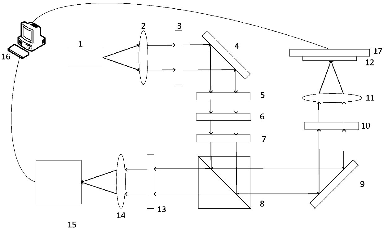
[0070] Such as figure 2 As shown, the non-linear super-resolution microscopy device that uses a nano-moving platform to scan samples includes a high-power laser 1, a first lens 2, a polarizer 3, a first mirror 4, a 0-2π vortex phase plate 5, and a second A quarter-wave plate 6, a half-wave plate 7, a dichroic mirror 8, a second mirror 9, a second quarter-wave plate 10, an objective lens 11, a sample 12, an optical filter 13, and a second lens 14 , a detector array 15 , a computer 16 and a nanomobile platform 17 .

[0071] use figure 2 The shown device realizes the non-linear differential microscopy method, and the procedure is as follows:

[0072] (1) The laser 1 emits high-intensity illumination light, which is collimated and expanded by the first lens 2; the illumination light after collimation and expansion passes through the polarizer 3 and becomes linearly polarized light;

[0073] (2) The linearly polarized light enters the 0~2π vortex phase plate 5 for phase modula...

Embodiment 2

[0078] Such as Figure 4 As shown, a non-linear super-resolution microscopy device that realizes sample scanning by galvanometer scanning, including a high-power laser 1, a first lens 2, a polarizer 3, a first mirror 4, and a 0-2π vortex phase plate 5 , the first quarter-wave plate 6, the half-wave plate 7, the dichroic mirror 8, the two-dimensional scanning galvanometer 18, the second quarter-wave plate 10, the objective lens 11, the sample 12, the filter 13, the first Two lenses 14, a detector array 15 and a computer 16.

[0079] use figure 2 The shown setup implements a nonlinear super-resolution microscopy method, the process of which is as follows:

[0080] (1) The laser 1 emits high-intensity illumination light, which is collimated and expanded by the first lens 2; the illumination light after collimation and expansion passes through the polarizer 3 and becomes linearly polarized light;

[0081] (2) The linearly polarized light enters the 0~2π vortex phase plate 5 fo...


PUM


Abstract

The invention discloses a non-linear super-resolution microscopic method adopting photon recombination. The method comprises steps as follows: 1), an illuminating beam after collimation and beam expanding is converted into linear polarization light, the linear polarization light is modulated into circular polarization light and is focused on a fluorescence sample, and hollow light spots are formed for illumination; 2), the fluorescence sample is stimulated to emit saturated fluorescence, and fluorescence imaging is realized by a detector array consisting of multiple photoelectric detectors; 3), the hollow light spots detected by the detectors are subjected to corresponding translation and then are overlaid, an image of a first solid light spot is obtained, and imaging of a corresponding scanning point is realized. The invention further discloses a non-linear super-resolution microscopic device adopting the photon recombination. According to the method and the device, the non-linear effect of fluorescence is realized through high-power laser illumination, a single pinhole detector arranged on an image surface in traditional confocal microscopic imaging is replaced with the pinhole detector array, the photon recombination technology is adopted, the device is simplified, and the imaging speed is increased.

Description

technical field [0001] The invention belongs to the field of confocal microscopy, in particular to a nonlinear super-resolution microscopy method and device for photon recombination. Background technique [0002] For a long time, due to the existence of the diffraction limit, the traditional far-field fluorescence microscopy technology has been greatly restricted in the application of nanotechnology, materials, biology and medical fields. To solve this problem, many super-resolution microscopy methods have been proposed since the 1990s. Among these proposed methods, fluorescence differential microscopy (FED) has become a newly proposed method in which biological samples can be analyzed without the use of fluorescent labels. Fluorescence differential microscopy is based on confocal microscopy imaging, which uses the difference between two images scanned by a specific excitation spot to obtain an increase in resolution. That is, the sample to be analyzed is illuminated by a ...

Claims


Application Information

Patent Timeline
Patent Type & Authority Applications(China)
IPC IPC(8): G01N21/64
CPCG01N21/6458G01N21/6402
Inventor 刘旭刘秋兰匡翠方刘少聪
Owner ZHEJIANG UNIV
Why Eureka
Try Eureka