Device with an illuminated button assembly

a technology of illuminated buttons and devices, applied in the field of illuminated buttons, can solve the problems of increasing the complexity and cost of buttons, limiting the aesthetics and functionality of buttons, and unable to provide fluid seals, etc., and achieve the effect of facilitating the movement of light guides

Active Publication Date: 2012-07-03
THE GILLETTE CO
View PDF70 Cites 18 Cited by
  • Summary
  • Abstract
  • Description
  • Claims
  • Application Information

AI Technical Summary

Benefits of technology

[0004]In one aspect, the invention features, in general, a button assembly for displaying an illuminated symbol. The button assembly has a locking ring and a solid light guide positioned within and spaced apart from the locking ring. The light guide has a top surface for displaying an illuminated symbol and a bottom surface with a light receiving member having a refracting surface with a first lens member for receiving and directing light to the top surface of the light guide. The button assembly also has a resilient sealing member mounted on the locking ring and interconnecting the locking ring and the light guide. The sealing member has an unsupported portion that facilitates movement of the light guide relative to the locking ring.

Problems solved by technology

However, when such devices are used in a wet environment, providing a functional button and a fluid seal can be problematic.
Providing a seal increases the complexity and cost of the button as well as limits the aesthetics and functionality of the button.
The seal can also limit assembly and installation of the button to the housing.
For example, elastomeric type push buttons that are used for sealing purposes do not provide the tactile and secure feedback of a rigid push button.
The transparent portion associated with the lighting means does not provide a uniform light over the top surface of the button.
These buttons have a combination of dim and bright light impressions on the top surface of the button, resulting in a visually non aesthetic display.
Providing a uniform light on the top surface of a button becomes even more problematic if the top surface of the button has both illuminated portions and non-illuminated portions.
A device having an illuminated portion of the button and a seal further increases the complexity and cost of the button, and is thus usually limited to larger household appliances.
Typically consumer products, such as shaving razors, have not had much added functionality, because of size and cost limitations.

Method used


Image

  • Device with an illuminated button assembly
  • Device with an illuminated button assembly
  • Device with an illuminated button assembly

Examples


Embodiment Construction

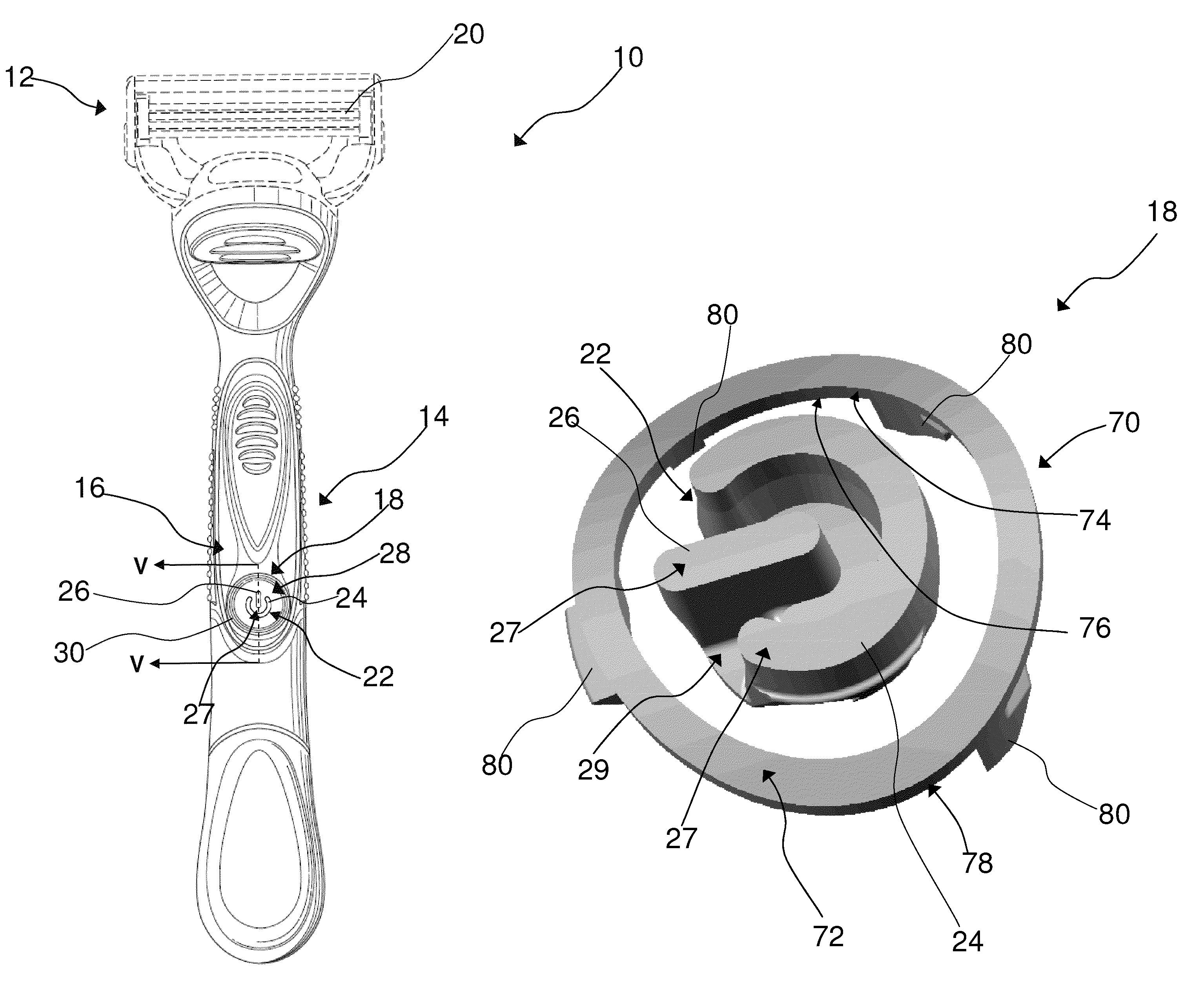
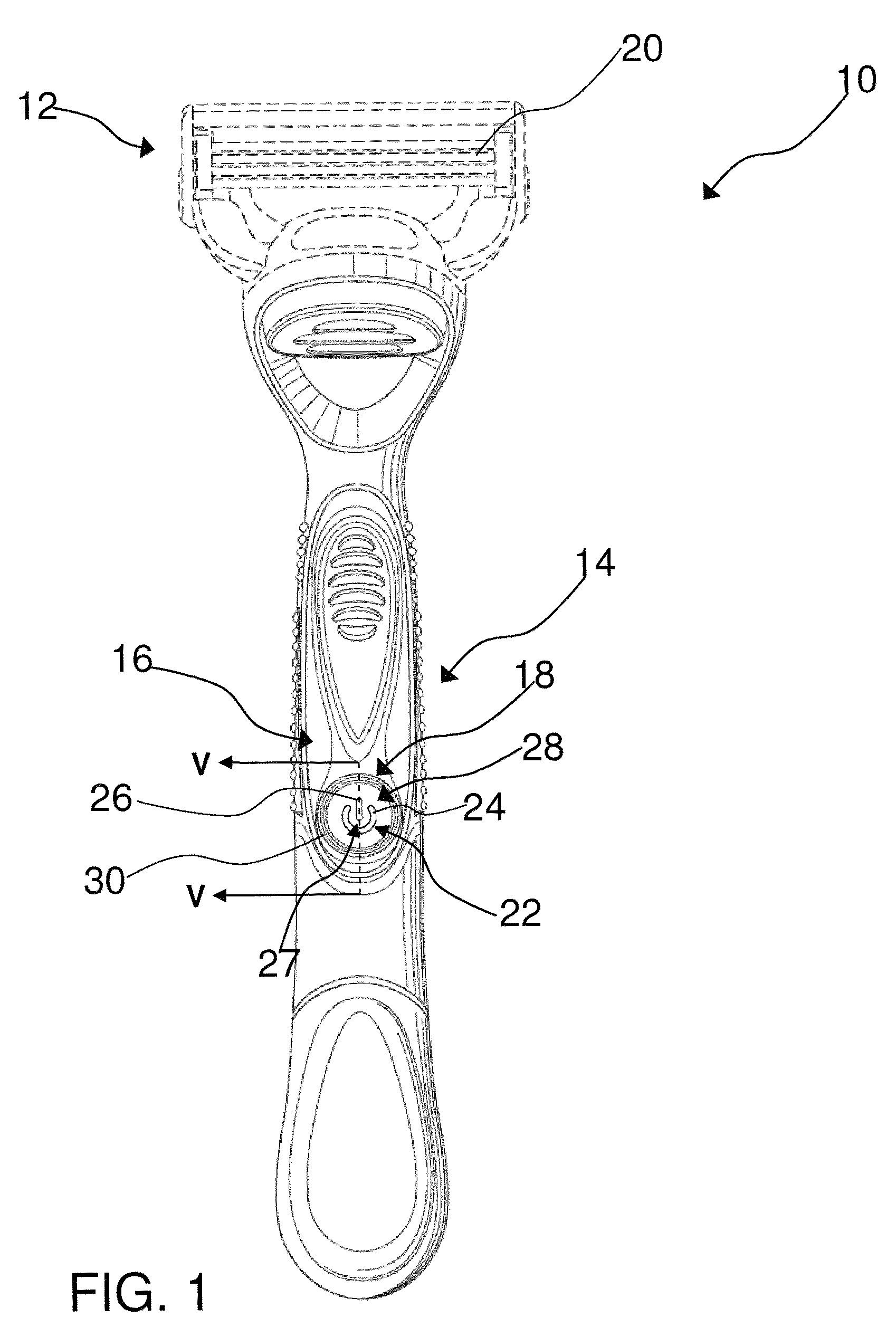
[0013]Referring to FIG. 1, one possible embodiment of the present invention is shown illustrating a shaving system 10 that includes a cartridge 12 mounted to a handle 14 having a top portion 16 with a button assembly 18. Although a wet shaving system is shown, the button assembly 18 may be utilized on any electronic grooming appliance that may be used in wet environments, such as toothbrushes or dry shaving razors. It may be advantageous for the button assembly 18 to be in close vicinity with an illuminated symbol, which allows consumers to intuitively understand product functionality. For example, an illuminated symbol may be integral with the button assembly 18 for communicating to the user that power to a light source and / or motor is on. The cartridge 12 may carry at least one blade 20 for shaving or trimming hair on the surface of skin. The cartridge 12 may be fixed or pivotably movable relative to the handle 14. In certain embodiments, the cartridge 12 may be mounted detachably...


PUM


Abstract

A button assembly for displaying an illuminated symbol has a locking ring and a solid light guide positioned within and spaced apart from the locking ring. The light guide has a top surface for displaying an illuminated symbol and a bottom surface with a light receiving member having a refracting surface with a first lens member for receiving and directing light to the top surface of the light guide. A resilient sealing member interconnects the locking ring and the light guide. The resilient sealing member is mounted on the locking ring and interconnects the locking ring and the light guide. The sealing member has an unsupported portion that facilitates movement of the light guide relative to the locking ring.

Description

FIELD OF THE INVENTION[0001]The present invention relates to a button assembly for actuating a switch or other mechanism that requires actuation and more particularly to an illuminated button for small electronic appliances used in wet environments, such as a wet shaving razor or other grooming devices.BACKGROUND OF THE INVENTION[0002]Powered electronic devices are commonly provided with button assemblies that allow switches, or other mechanisms mounted within the housing of the device, to be actuated from outside of the device. However, when such devices are used in a wet environment, providing a functional button and a fluid seal can be problematic. Providing a seal increases the complexity and cost of the button as well as limits the aesthetics and functionality of the button. The seal can also limit assembly and installation of the button to the housing. For example, elastomeric type push buttons that are used for sealing purposes do not provide the tactile and secure feedback o...

Claims


Application Information

Patent Timeline
Patent Type & Authority Patents(United States)
IPC IPC(8): B26B19/00H01H13/14H01H19/00H01H3/12H01H9/00
CPCB26B21/4062H01H13/023H01H13/06H01H2219/062H01H2219/0622H01H2221/084H01H2223/002
Inventor SCHNAK, FREDREHBEIN, STEFANLASCHINSKI, GERDAMSEL, KLAUS GUNTHERHUBSCHER, WERNERLESSIAK, HERBERT
Owner THE GILLETTE CO
Why Eureka
Try Eureka