
A dynamic reactive power compensation control method and system for a photovoltaic grid-connected inverter

A photovoltaic inverter, compensation control technology, applied in the direction of reactive power compensation, reactive power adjustment/elimination/compensation, photovoltaic power generation, etc., can solve the problems of low test accuracy, wrong compensation, etc. Calculation space, effect of increasing reliability

Active Publication Date: 2017-01-25
CSIC HAIWEI ZHENGZHOU HIGH TECH CO LTD
View PDF5 Cites 0 Cited by
  • Summary
  • Abstract
  • Description
  • Claims
  • Application Information

AI Technical Summary

Problems solved by technology

[0004] The shortcomings of the traditional calculation method of reactive power compensation rate of photovoltaic inverters are: 1. There is a defect of low test accuracy in the single control based on the degree of grid voltage drop; 2. value and the voltage drop speed is fast, it is easy to cause false compensation

Method used


Image

  • A dynamic reactive power compensation control method and system for a photovoltaic grid-connected inverter
  • A dynamic reactive power compensation control method and system for a photovoltaic grid-connected inverter

Examples


Embodiment Construction

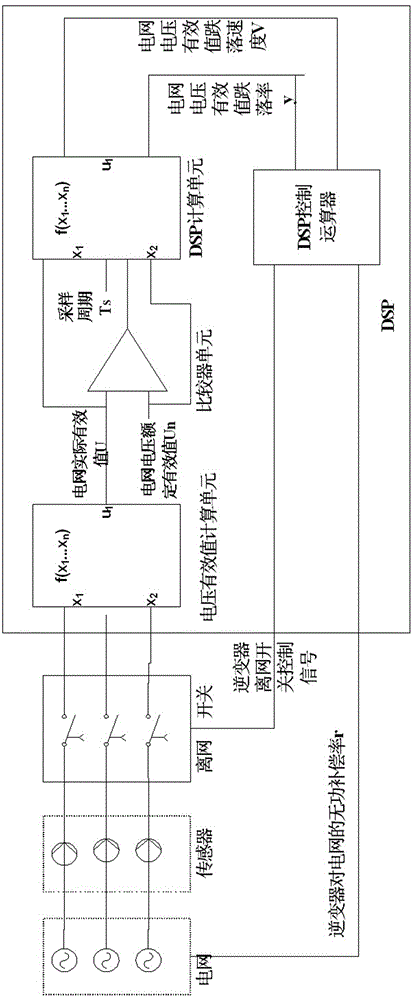
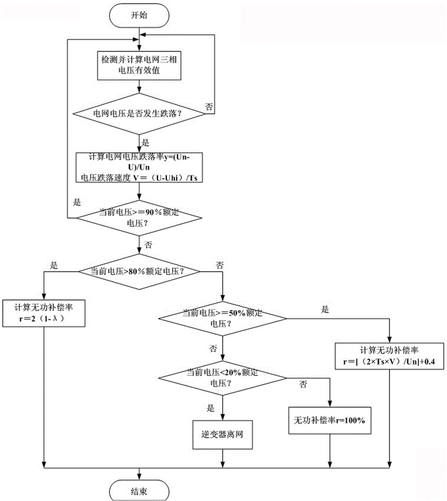
[0029] like figure 2 As shown, a dynamic reactive power compensation control method for photovoltaic grid-connected inverters, the sensor detects the effective value of the three-phase voltage of the power grid in real time, and calculates and analyzes the change degree of the effective value of the three-phase voltage of the power grid through PID control, and the three-phase voltage The minimum value is used as the control quantity to detect the state of the grid voltage; when the grid voltage drops, the grid voltage effective value drop rate y and the grid voltage drop speed V are calculated;

[0030] y=(Un-U) / Un

[0031] V=(U-Uhi) / Ts

[0032] Where Un is the effective value of the grid rated voltage, U is the current effective value of the grid voltage, Uhi is the effective value of the grid voltage at the last sampling time, and Ts is the sampling period;

[0033] Input the two control quantities of grid voltage RMS drop rate y and grid voltage drop speed V into the DS...


PUM


Abstract

The invention relates to a method for dynamic inactive compensation control of a photovoltaic grid-connected inverter. The method comprises the following steps of enabling a sensor to detect the effective value of three-phase voltage of a power grid in real time, calculating and analyzing the change degree of the effective value of the three-phase voltage of the power grid through PID (proportion integration differentiation) control, using the minimum value of the three-phase state as the control quantity, and detecting the voltage states of the power grid; when the voltage of the power grid drops, calculating the dropping rate y of the effective value of the voltage of the power grid and the dropping speed V of the voltage of the power grid; inputting the two control quantities, namely the dropping rate y of the effective value of the voltage of the power grid and the dropping speed V of the voltage of the power grid, into a DSP (digital signal processor) controller, and respectively controlling the inactive compensation rates of a photovoltaic inverter off-grid switch and the photovoltaic inverter. The method has the advantage that the inactive compensation rate of the photovoltaic inverter is controlled by two control factors, namely the voltage dropping degree and the voltage dropping speed, the mutual supplementing function of the two control factors in the sudden dropping process of the voltage of the power grid is utilized, the possible false compensation of the photovoltaic inverter on the power grid is avoided, and the reliability of inactive compensation software is improved.

Description

technical field [0001] The invention belongs to the technical field of reactive power compensation for power grids by grid-connected photovoltaic grid-connected inverters, and specifically relates to a segmented control method that uses grid voltage drop degree and drop speed to control reactive power compensation rate of photovoltaic inverters and its Control System. Background technique [0002] Photovoltaic inverters, as the main components of solar power generation systems, have received attention from various aspects of society in recent years. The country's requirements for the development and production technology of photovoltaic inverters are also constantly improving. In 2010, the national standard "Technical Requirements and Test Methods for Inverters for Grid-Connected Photovoltaic Power Generation" was promulgated. The ability to withstand the abnormal voltage of the power grid, and the ability to adjust the reactive power output according to the voltage level ...

Claims


Application Information

Patent Timeline
Patent Type & Authority Patents(China)
IPC IPC(8): H02J3/18
CPCH02J3/16H02J3/383Y02E10/56Y02E40/30
Inventor 张蕾谢战洪王笑非王大鹏高瑛
Owner CSIC HAIWEI ZHENGZHOU HIGH TECH CO LTD
Learn More