Blind apparatus

A shutter device and blade technology, which is applied to door/window protection devices, shutters/movable grilles, windows/doors, etc., can solve the problems of occupying space, difficult to reduce the setting area of ​​shutter devices, etc., and achieve the effect of stable opening of openings

Inactive Publication Date: 2015-03-18
OILES ECO CORP
View PDF6 Cites 4 Cited by
  • Summary
  • Abstract
  • Description
  • Claims
  • Application Information

AI Technical Summary

Problems solved by technology

In addition, in the shutter device, when the window is fully opened, it is preferable to arrange a plurality of blades that overlap each other and are gathered on the ceiling side without greatly covering the top of the window, so as not to affect the field of view when viewing from the window, and if necessary, obtain enough. However, due to the space taken up by the lift mechanism of the blades or the tilting mechanism of the blades, if the height of the ceiling is not increased, the multiple blades folded may cover the top of the window substantially
In addition, in the louver device, in order to incline the plurality of blades in the front-rear direction of the blades around a fixed rotation axis by the tilting mechanism, the leading edge portions of the blades protrude forward, so that the size of the louver device itself and the its setting area

Method used


Image

  • Blind apparatus
  • Blind apparatus
  • Blind apparatus

Examples


Embodiment Construction

[0055] Next, embodiments of the present invention will be described in more detail based on preferred examples shown in the drawings. It should be noted that the present invention is not limited to these examples.

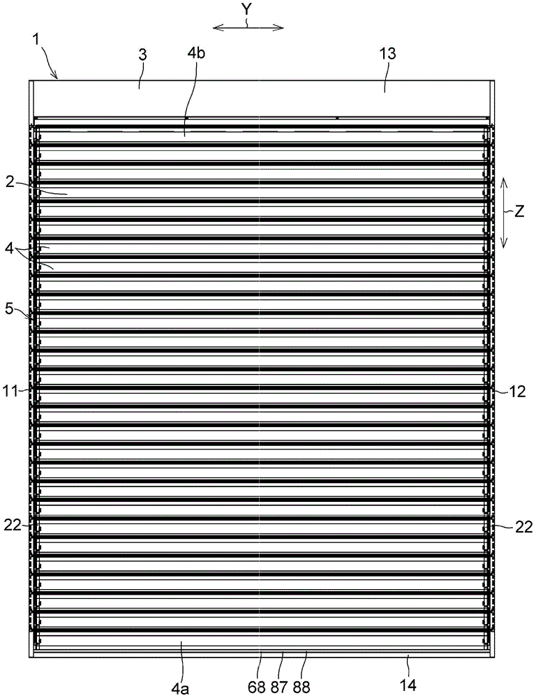
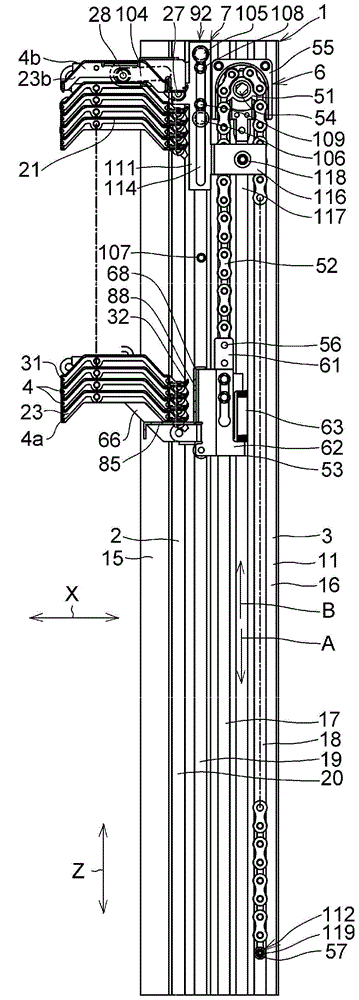
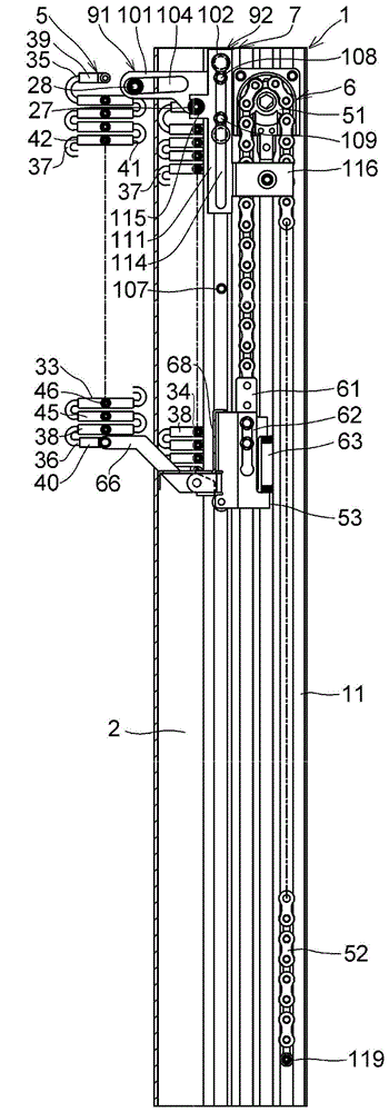
[0056] exist Figure 1 to Figure 19 Among them, the shutter device 1 of this example has: a frame body 3 formed with an opening 2; a plurality of blades 4 arranged side by side in the opening 2 along the up-down direction (vertical direction), that is, the Z direction; the plurality of blades 4 are connected to each other A link mechanism 5; a lifting mechanism 6 that makes a plurality of blades 4 rise or fall from the bottom blade 4a; The rear of the blade 4b, and the tilting mechanism 7 that tilts the plurality of blades 4 by raising or lowering the blades 4 by the lifting mechanism 6 .

[0057] For example figure 1 As shown, the frame body 3 has a pair of vertical frames 11 and 12, a top frame 13, and a bottom frame 14, wherein the pair of vertical frames 11 ...


PUM


Abstract

A blind apparatus (1) comprises: a frame body (3) defining an opening (2); a plurality of blades (4) arranged mutually parallel in the opening (2) in the Z direction; a link mechanism (5) mutually coupling the plurality of blades (4); a lifting mechanism (6) that lifts and lowers from the bottommost blade (4a) of the plurality of blades (4); and a tilting means (7) that is disposed at the back of the blades (4) and tilts the plurality of blades (4) on the basis of the lifting or lowering of the blade (4a) by way of the lifting mechanism (6).

Description

technical field [0001] The present invention relates to a shutter device arranged on a window of a building so as to shade and light-shield a room. Background technique [0002] There is a known shutter device, which arranges a plurality of blades (slat) in the up and down direction on the window of the building, and through the lifting and tilting of the blades, the room is covered while natural light or artificial light is blocked, for example, patent The blind device disclosed in Document 1 is provided with: a lifting device for raising or lowering the blades; and a tilting mechanism for tilting the blades. In the shutter device installed on the indoor side or the outdoor side, when the window is fully opened, a plurality of overlapping and folded blades are generally arranged on the ceiling side. In addition, in the shutter device, when the window is fully opened, it is preferable to arrange a plurality of blades that overlap each other and are gathered on the ceiling s...

Claims


Application Information

Patent Timeline
Patent Type & Authority Applications(China)
IPC IPC(8): E06B9/322E06B9/02E06B9/302
CPCE06B9/0676E06B9/322E06B9/0638E06B9/302E06B9/32E06B2009/3222
Inventor 大石守
Owner OILES ECO CORP
Why Eureka
Try Eureka