Connecting structure of flexible belts of wearable products
A technology of connecting structure and flexible belt, applied in the direction of belt buckle, clothing, application, etc., can solve the problems of discomfort and trouble in assembly and disassembly of flexible belt, and achieve the effect of avoiding discomfort, solving trouble in assembly and disassembly, and convenient in assembly and disassembly.
- Summary
- Abstract
- Description
- Claims
- Application Information
AI Technical Summary
Problems solved by technology
Method used
Image
Examples
no. 1 example
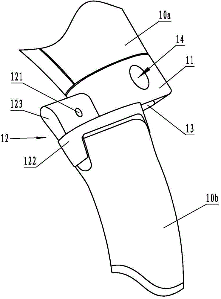
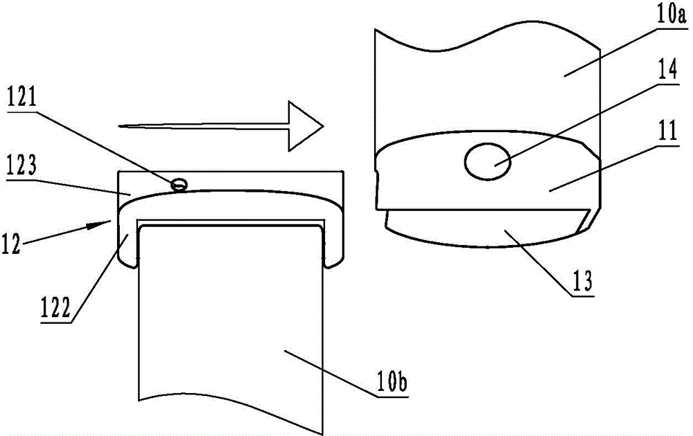
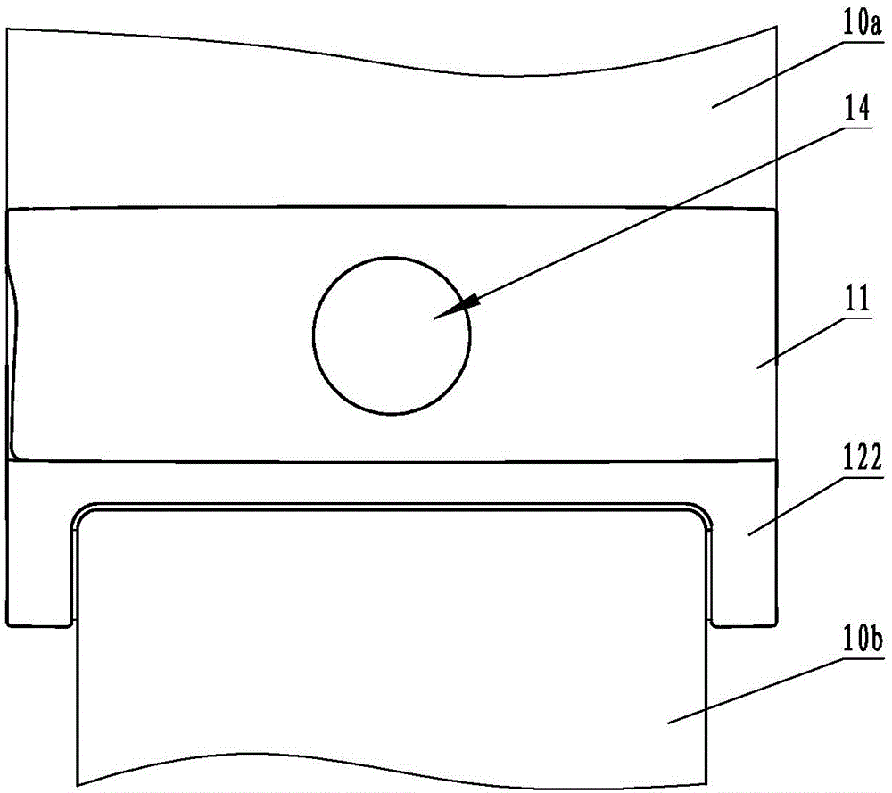
[0029] Depend on Figure 1 to Figure 6 It can be seen that the connection structure of the flexible belt of the wearable product includes: a first fixed connector 11 provided at the end of the flexible belt 10a on one side of the worn product, and a second fixed connector 12 provided at the end of the flexible belt 10b on the other side of the worn product. A fixed connector 11 is provided with an accommodating cavity 13 for accommodating the second fixed connector 12, and a limiting groove 121 is provided on the second fixed connector 12 corresponding to the side wall of the accommodating cavity 13. A push-type lock release switch 14 is provided between the side wall of the accommodation cavity 13 of the component 11 and the limiting groove 121 of the second fixed connection piece 12, and the push-type lock release switch 14 includes an inner wall arranged on the side wall of the accommodation cavity 13. In the cavity, the connecting piece 141 that is rotatably connected to t...
no. 2 example
[0036] Depend on Figure 7 , Figure 8 It can be seen that this embodiment is basically the same as the first embodiment, the differences are:
[0037] An elastic pop-up piece 17 is disposed in the accommodating cavity 13 , and the installation direction of the elastic pop-up piece 17 is the same as the insertion direction of the locking tongue 123 . When in use, press the button 142, and the thimble 143 is lifted and disengaged from the limit groove 121 under the force of leverage. At this time, under the elastic force of the elastic pop-up member 17, the lock tongue 123 is automatically ejected from the accommodating cavity 13, saving time and effort. It's very convenient.
no. 3 example
[0039] Depend on Figure 9 It can be seen that this embodiment is basically the same as the second embodiment, the differences are:
[0040] The elastic return mechanism is a torsion spring 19 , which is sheathed on the rotating shaft 15 , one end of which is fixedly connected to the connector 141 , and the other end is fixedly connected to the inner cavity side wall of the side wall of the accommodating cavity 13 .
PUM
 Abstract
Description
Claims
Application Information
 - R&D
- Intellectual Property
- Life Sciences
- Materials
- Tech Scout
- Unparalleled Data Quality
- Higher Quality Content
- 60% Fewer Hallucinations
Browse by: Latest US Patents, China's latest patents, Technical Efficacy Thesaurus, Application Domain, Technology Topic, Popular Technical Reports.
© 2025 PatSnap. All rights reserved.Legal|Privacy policy|Modern Slavery Act Transparency Statement|Sitemap|About US| Contact US: help@patsnap.com


