Trimming and punching die

A technology of edge trimming punching die and punching punch, which is applied in the direction of perforating tools, metal processing equipment, forming tools, etc., can solve the problem of large size of the slider, and achieve the effect of solving the effect of large overall size of the mold

Active Publication Date: 2015-03-25
ANHUI JIANGHUAI AUTOMOBILE GRP CORP LTD
View PDF6 Cites 0 Cited by
  • Summary
  • Abstract
  • Description
  • Claims
  • Application Information

AI Technical Summary

Problems solved by technology

[0004] The purpose of this invention is to provide a kind of trimming punching die, to solve the problem that the size of the slide block must be larger in the prior art

Method used


Image

  • Trimming and punching die
  • Trimming and punching die
  • Trimming and punching die

Examples


Embodiment Construction

[0022] In order to enable those skilled in the art to better understand the technical solutions of the present invention, the present invention will be further described in detail below in conjunction with the accompanying drawings.

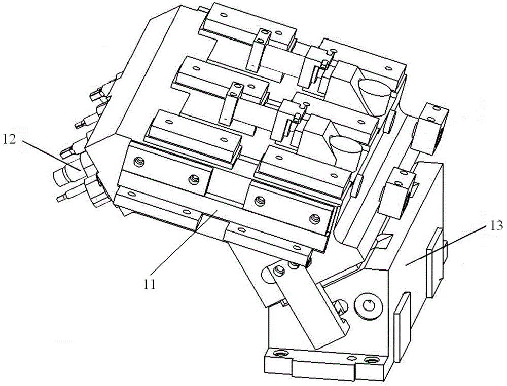
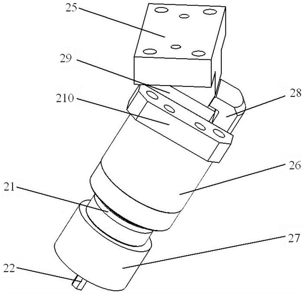
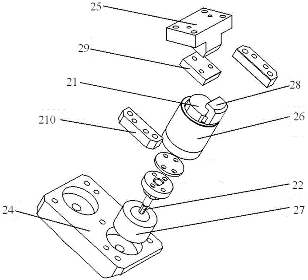
[0023] Such as Figure 2-5 As shown, a kind of edge trimming punching die provided by the embodiment of the present invention includes an upper die base and a pressing core 24, and also includes a driving block 25, a slide block 21, a guide sleeve 26, a punching punch 22 and an elastic member 27, and the driving The block 25 is fixed on the upper mold base, the guide sleeve 26 and the elastic member 27 are arranged on the pressing core 24, the punching punch 22 is fixed on the lower end of the slide block 21, the slide block 21 is slidably connected with the guide sleeve 26, and the slide block 21 is set by The drive block 25 above it drives, and the lower end of the slide block 21 overlaps on the elastic member 27 .

[0024] Specifically, when ...


PUM


Abstract

The invention discloses a trimming and punching die which comprises an upper die base and a material pressing core. The trimming and punching die further comprises a driving block, a sliding block, a guide sleeve, a punching male die and an elastic piece. The driving block is fixed on the upper die base, the guide sleeve and the elastic piece are arranged on the material pressing core, and the punching male die is fixedly arranged at the lower end of the sliding block. The sliding block and the guide sleeve are in sliding connection, the sliding block is driven by the driving block which is arranged above the sliding block, and the lower end of the sliding block is in lap joint to the elastic piece. According to the trimming and punching die, the size of the sliding block can be correspondingly decreased compared with the prior art, and thus the series of problems that the overall size of a die is large, and the power needed for driving and restoring the sliding block is large in the prior art are solved at the same time.

Description

technical field [0001] The invention relates to mechanical processing equipment, in particular to a trimming and punching die. Background technique [0002] In fields such as automobile manufacturing, it is often necessary to perform flanging, punching and trimming operations on large-area panels. figure 1 It is a partial schematic diagram of a trimming punching die in the prior art; as figure 1 As shown, the trimming punching die includes a punching punch 12, a slide block 11 and a lower drive block 13, one end of the slide block 11 is fixed to the punch punch 12, and the other end of the slide block 11 is slidably connected with the lower drive block 13 through a wedge structure. , the lower driving block 13 is fixed on the lower mold base (not shown in the figure) of the trimming punching die. In the middle, the slide block 11 is forced to move down and thereby drives the punching punch 12, and the punching punch 12 is pressed against the plate to complete the punching ...

Claims


Application Information

Patent Timeline
Patent Type & Authority Applications(China)
IPC IPC(8): B21D37/10B21D28/34
CPCB21D28/34B21D37/10
Inventor 陈世涛王海玲何鹏申黄涛郭奔李辉
Owner ANHUI JIANGHUAI AUTOMOBILE GRP CORP LTD
Why Eureka
Try Eureka