Gap part aligning and mistaken delivery detecting structure

A technology of misfeed detection and notch, applied in the field of notch parts guide and misfeed detection and guide structure, it can solve the problems of inapplicability, misfeed of guide pin positioning, unable to correct in time, etc., to achieve good positioning effect and not easy to deviate. , the effect of reducing waste

Active Publication Date: 2015-03-25
WUXI MICRO RES
View PDF8 Cites 3 Cited by
  • Summary
  • Abstract
  • Description
  • Claims
  • Application Information

AI Technical Summary

Problems solved by technology

[0003] In the prior art, the guide pin is usually installed on the upper die. When the upper die moves downward, the guide pin is first inserted into the strip material so that the strip material is positioned in the mold, and then the punch punches it out. However, this kind of The method is not suitable for the situation in which it is used
For example, for products with simple punching but uneven edges, it does not have a good guiding effect, such as image 3 The material strip 7 with notches shown requires two square notches 701 to be punched out on both sides, and a square hole 702 to be punched out in the middle, and then to be cut off, and the guiding nails at the notches cannot be well guided; Positive nail positioning may cause misfeeding, which cannot be corrected in time

Method used


Image

  • Gap part aligning and mistaken delivery detecting structure
  • Gap part aligning and mistaken delivery detecting structure
  • Gap part aligning and mistaken delivery detecting structure

Examples


Embodiment Construction

[0015] The specific embodiments of the present invention will be described below in conjunction with the drawings.

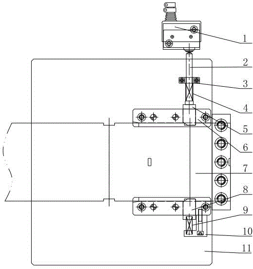
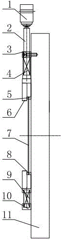
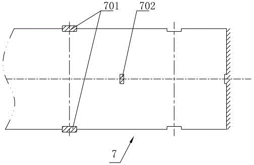
[0016] Such as figure 1 , figure 2 As shown, the notch component guide and misfeed detection structure of this embodiment includes a concave mold 11, a material belt 7 conveyed by a feeder is arranged in the middle of the concave mold 11, and evenly-spaced gaps 701 are opened on both sides of the material belt 7. On the mold 11, a symmetrically arranged strip guide plate 6 is fixed by fasteners. The guide plates 6 are respectively located on both sides of the strip 7; the first push block 5 is installed on the guide plate 6 at the upper end. An associated pin 2 is installed at the upper end of the push block 5, a first spring 4 is sleeved on the associated pin 2, and the associated pin 2 passes through the fixed block 3 installed on the die 11; the second push block 8 is installed on the guide plate 6 at the lower end , The guide plate 6 at the lower end is also...


PUM


Abstract

The invention relates to a gap part aligning and mistaken delivery detecting structure. The gap part aligning and mistaken delivery detecting structure comprises a female die. A material belt conveyed by a material conveyer is arranged in the middle of the female die. The two sides of the material belt are provided with gaps which are evenly arranged at equal intervals. Symmetrical material guiding plates are fixed to the female die through fastening pieces. The material guiding plates are located on the two sides of the material belt respectively. The material guiding plate located at the upper end is provided with a first pushing block. An association pin is installed at the upper end of the first pushing block. The association pin is sleeved with a first spring. The association pin penetrates through a fixing block installed on the female die. The material guiding plate located at the lower end is provided with a second pushing block. The material guiding plate located at the lower end is further provided with a stop block of a right-angled structure through a fastening piece. One right-angled edge of the stop block is connected with the second pushing block through a second spring. The gap part aligning and mistaken delivery detecting structure further comprises a mistaken delivery detector. The mistaken delivery detector is installed on one side of the female die. A contact switch of the mistaken delivery detector is in butt joint with the head of the associated pin. The pushing blocks are connected with the corresponding gaps of the material belt in matched and clamped modes, so that the material belt achieves a good locating effect and is not prone to deviation, and rejected products can be greatly reduced.

Description

Technical field [0001] The invention relates to the technical field of stamping parts guide, in particular to a guide structure for notched parts guide and misfeed detection. Background technique [0002] In the current use of progressive die stamping products, the correcting of the tape is a very important process. If the tape is not correctly guided, a lot of waste will be produced when stamping is started. [0003] In the prior art, the guide pin is usually installed on the upper mold. When the upper mold moves downward, the guide pin is inserted into the strip material to position the strip material in the mold, and then the punch is punched. The method is not suitable for all occasions. For example, for simple blanking, products with uneven edges cannot achieve a good correction effect, such as image 3 The shown material belt 7 with notches needs to punch out two square notches 701 on both sides, punch a square hole 702 in the middle, and then cut it off. Using guide pins at ...

Claims


Application Information

Patent Timeline
Patent Type & Authority Applications(China)
IPC IPC(8): B21D43/00B21C51/00
CPCB21C51/00B21D43/003
Inventor 朱其红陈兆茂
Owner WUXI MICRO RES
Why Eureka
Try Eureka