Piston with venting device for hydraulic traction mechanism tensioner

A technology of traction mechanism and tensioning device, which is applied in the direction of transmission device, mechanical equipment, belt/chain/gear, etc., and can solve the problem of unreliable exhaust.

Active Publication Date: 2018-11-13
SCHAEFFLER TECH AG & CO KG
View PDF6 Cites 0 Cited by
  • Summary
  • Abstract
  • Description
  • Claims
  • Application Information

AI Technical Summary

Problems solved by technology

Furthermore, there is a problem with the position of the exhaust duct or the exhaust opening in the cover element, since the cover element is designed to rest on the tensioning rail, it can happen that the tension rail is briefly in the contact point cover the exhaust opening so that it cannot be reliably exhausted

Method used


Image

  • Piston with venting device for hydraulic traction mechanism tensioner
  • Piston with venting device for hydraulic traction mechanism tensioner

Examples


Embodiment Construction

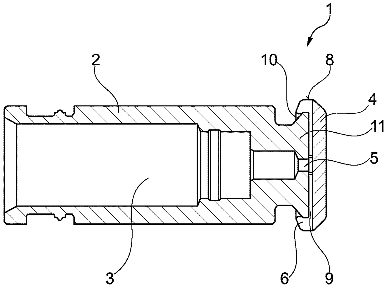
[0011] figure 1 A cross-section through a piston according to the invention is shown, which is provided for use in a hydraulic traction mechanism tensioning device. The piston 1 has a cylinder-shaped housing 2 with a hollow chamber 3 for receiving oil. The hollow chamber 3 is designed as a high-pressure chamber in which an oil pressure builds up. Since air has different compression properties than oil, it is desirable to divert the air contained in the hollow chamber. For this reason, through-holes are arranged in the top 11 of the housing 2 , through which air can escape from the hollow chamber 3 or the high-pressure chamber of the piston 1 . The piston 1 is usually made of steel or aluminum and rests on a tensioning rail, which is usually made of plastic or another lightweight material. During operation, the piston 1 presses against the tensioning rail, causing wear on the tensioning rail in the contact region due to the harder piston material. It is known to arrange a ...


PUM


Abstract

Piston (1) for a hydraulic mechanism tensioning device of a flexible drive in an internal combustion engine comprising a pot-like housing (2) having a cavity (3) for receiving oil and one in the bottom (11) of the housing (2) arranged through bore (5), and a from outside the housing (2) on the base (11) attachable cap (4), on which bears the piston (1) to a clamping rail of the flexible drive, wherein the cap (4) on its bottom (11) of the housing (2) directed towards the inner surface (12) has at least one groove-like depression (9). According to the utility model, continuous and reliable air discharging can be ensured.

Description

technical field [0001] A piston for a hydraulic traction mechanism tensioner for a traction mechanism transmission in an internal combustion engine. The piston has a cylinder-shaped housing with a hollow chamber for receiving oil and a cap that can be inserted onto the top from the outside of the housing. A through hole is arranged in the top of the housing. By means of this cap, the piston can be supported on the tensioning rail of the traction mechanism transmission. Background technique [0002] A piston according to the aforementioned category is known from patent document EP2013515B1. The document shows a tensioning device with a piston having a groove on its end side and a covering element into which the covering element fits so that a third of the covering element extends beyond the edge of the piston, the covering element like The cap rests against the end face. The end face of the piston and the covering element have through holes. The two holes are arranged ve...

Claims


Application Information

Patent Timeline
Patent Type & Authority Patents(China)
IPC IPC(8): F16H7/08
CPCF16H7/0848F16H2007/0806F16H2007/0817
Inventor 多米尼克·霍夫曼
Owner SCHAEFFLER TECH AG & CO KG
Why Eureka
Try Eureka