
Gate valve sealing structure

A sealing structure and gate valve technology, applied in sliding valves, valve devices, engine components, etc., can solve problems such as failure of transmission pair, large gap between casting and valve body guide groove width, etc. The effect of seal failure

Inactive Publication Date: 2015-03-25
SUZHOU WUZHONG DISTRICT DALU ELECTRIC EQUIP FACTORY
View PDF7 Cites 4 Cited by
  • Summary
  • Abstract
  • Description
  • Claims
  • Application Information

AI Technical Summary

Problems solved by technology

[0002] The gate valve has simple structure and reliable performance, and is widely used in petrochemical, refining, oil and gas, city gas and other flammable and explosive hazardous occasions. In the previous production of valve products, the gap between the casting and the width of the guide rail groove of the valve body is relatively large. During the opening and closing process, the rod is not only affected by the pressure of the medium, but also by the gravity of the gate and the medium. When the valve is installed in a vertical pipeline or installed on the side of a horizontal pipeline, the opening and closing torque of the valve is increased during the opening and closing process. , also accelerates the wear between the valve stem and the stem nut transmission pair, and even causes premature failure of the transmission pair, therefore, it needs to be improved

Method used


Image

  • Gate valve sealing structure

Examples


Embodiment Construction

[0011] The present invention will be explained below with reference to the drawings.

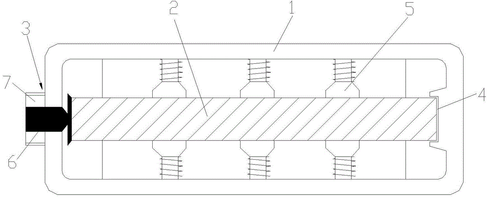
[0012] Attached figure 1 It is a gate valve sealing structure according to the present invention, which includes a valve body 1 and a gate 2; one end of the inner wall of the valve body 1 is provided with an adjusting jacking table 3, and the other end is provided with a guide rail 4; The tightening table 3 and the guide rail 4 are arranged in the valve body 1 in cooperation; the upper and lower ends of the gate 2 are provided with spring support columns 5, and the number of the spring support columns 5 is at least two groups, at least two in each group; The spring support column 5 pushes the gate plate 2 through the spring extension; the adjusting jacking table 3 includes a jacking rod 6 and a nut 7; one end of the jacking rod 6 pushes the gate plate 2 and the other end extends out of the valve body 1 and fix with nut 7.

[0013] According to a gate valve sealing structure of the present inven...


PUM


Abstract

The invention discloses a gate valve sealing structure. The gate valve sealing structure comprises a valve body and a gate plate. An adjusting and abutting table is arranged at one end of the inner wall of the valve body, a guide rail is arranged at the other end of the inner wall of the valve body. The gate plate is arranged in the valve body in the manner of being matched with the guide rail through the adjusting and abutting table. The upper end and the lower end of the gate plate are provided with spring supporting columns. The spring supporting columns abut against the gate plate through stretching of springs. The adjusting and abutting table comprises an abutting rod and a nut. One end of the abutting rod abuts against the gate plate, and the other end of the abutting rod extends out of the valve body and is fixed through the nut. According to the gate valve sealing structure, the adjusting and abutting table and the guide rail are arranged in the valve body, the upper end and the lower end of the gate plate are provided with the spring supporting columns, in this way, the state that floating valve seats of original similar valve products of vertical pipes or inclined pipes or other pipes are pressed by a gate plate and media through pressure for a long term is avoided, the problem that the floating valve seats are pressed for a long term and do not float, so that failure is caused is solved, the sealing failure phenomenon of the valve is eradicated, and the reliability of bidirectional sealing of the inlet end of the outlet end of the valve is guaranteed.

Description

Technical field [0001] The invention relates to a gate valve sealing structure and belongs to the technical field of gate valves. Background technique [0002] The gate valve is simple in structure and reliable in performance. It is widely used in petrochemical, refining, petroleum and natural gas, city gas and other flammable and explosive hazardous occasions. The valve products produced in the past have a large gap between the casting and the width of the valve body guide groove. In addition to the pressure of the medium during the opening and closing process, the rod is also affected by the gate and the gravity of the medium. When the valve is installed in a vertical pipeline or on the side of a horizontal pipeline, the opening and closing torque of the valve is increased during the opening and closing process. , It also accelerates the wear between the valve stem and the valve stem nut transmission pair, and even causes the transmission pair to fail prematurely. Therefore, it...

Claims


Application Information

Patent Timeline
Patent Type & Authority Applications(China)
IPC IPC(8): F16K3/30
CPCF16K3/30
Inventor 钱永清
Owner SUZHOU WUZHONG DISTRICT DALU ELECTRIC EQUIP FACTORY
Learn More