
Spherical valve

A technology of spherical valves and valve balls, applied to valve devices, cocks including cut-off devices, engine components, etc., can solve problems such as waste of resources, water run-off control, inconvenient maintenance, etc., achieve good sealing effect and prevent valve balls from moving , Easy to disassemble and maintain

Inactive Publication Date: 2015-03-25
SUZHOU FURUN MACHINERY
View PDF4 Cites 0 Cited by
  • Summary
  • Abstract
  • Description
  • Claims
  • Application Information

AI Technical Summary

Problems solved by technology

[0002] At present, the spherical valves sold in the market have unreasonable design of the valve ball and the driving handle, are easy to break and fall off, and are inconvenient to maintain after the damage, and the entire valve is often replaced, which not only causes water loss control, wastes resources, but also increases the use of cost
In addition, the sealing effect of the valve is not good, and it is easy to leak water when throttling, wasting resources

Method used


Image

  • Spherical valve
  • Spherical valve
  • Spherical valve

Examples


Embodiment Construction

[0016] In order for examiners to better understand the technical features, technical contents and technical effects of the present invention, the accompanying drawings of the present invention will now be described in more detail in conjunction with the embodiments. However, the drawings shown are only for better illustration of the technical solutions of the present invention, not the true scale and optimal configuration of the present invention, so the examiner is requested not to limit the scope of the present invention with respect to the ratio and configuration of the drawings Scope of claims.

[0017] Below in conjunction with accompanying drawing and embodiment the patent of the present invention is further described.

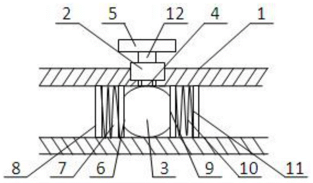
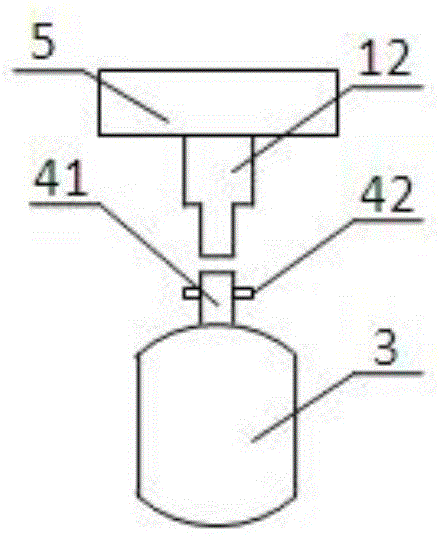
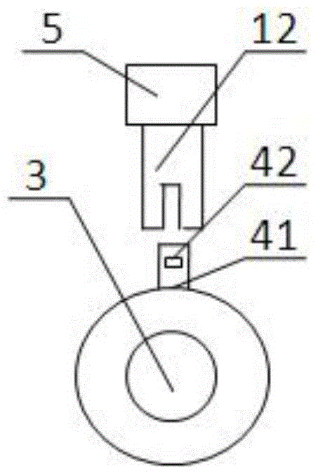
[0018] Such as Figure 1-3 As shown, the present invention provides a spherical valve, comprising a valve body 1, a valve stem 2, and a valve ball 3, the valve ball 3 is arranged in the valve body 1, and the upper end of the valve ball 3 is provided wit...


PUM


Abstract

The invention discloses a spherical valve which comprises a valve body, a valve rod and a valve ball. The spherical valve is characterized in that the valve ball is arranged inside the valve body, a connecting device is arranged at the upper end of the valve ball, the upper end of the valve ball is connected with the valve rod through the connecting device, the connecting device is a protrusion arranged on the valve ball, a lug is arranged on the protrusion, the valve ball is connected to a driving rod inside the valve rod in a clamped mode through the lug, one end of the valve ball is connected with a first sealing ring, the first sealing ring is connected with a first spring, the other end of the valve ball is connected with a second sealing ring, and the second sealing ring is connected with a second spring. Due to the facts that the protrusion is arranged on the valve ball, the lug is arranged on the protrusion, and the lug is connected with the driving rod inside the valve rod in a clamped mode, the valve ball can be prevented from moving through the connecting mode, and disassembly and maintenance are easy; in addition, due to the fact that the spring is connected to the sealing ring, the sealing effect is better, and water resource waste will not be caused when the valve is closed.

Description

technical field [0001] The invention relates to a valve, in particular to a spherical valve. Background technique [0002] At present, the spherical valves sold in the market have unreasonable design of the valve ball and the driving handle, are easy to break and fall off, and are inconvenient to maintain after the damage, and the entire valve is often replaced, which not only causes water loss control, wastes resources, but also increases the use of cost. In addition, the sealing effect of the valve is not good, and it is easy to leak water when throttling, wasting resources. Contents of the invention [0003] In order to solve the above-mentioned defects and deficiencies in the prior art, the present invention provides a spherical valve, which not only has a firm connection between the valve ball and the driving handle, is easy to disassemble and maintain, but also has a good sealing effect and will not cause waste of water resources. [0004] In order to solve the abo...

Claims


Application Information

Patent Timeline
Patent Type & Authority Applications(China)
IPC IPC(8): F16K5/06F16K5/08F16K5/20
CPCF16K5/0663F16K5/08F16K5/20
Inventor 张国红
Owner SUZHOU FURUN MACHINERY
Learn More