Air duct system, air supply method thereof and fan and air conditioner with air duct system

An air conditioner and air duct technology, which is applied in the field of air ducts, can solve the problems of low air output efficiency, achieve stable air supply volume, energy saving and environmental protection, and high energy efficiency utilization

Active Publication Date: 2015-03-25
GD MIDEA AIR-CONDITIONING EQUIP CO LTD
View PDF6 Cites 12 Cited by
  • Summary
  • Abstract
  • Description
  • Claims
  • Application Information

AI Technical Summary

Problems solved by technology

[0002] In the air duct structure in the prior art, grid-shaped air inlets and outlets are directly arranged on the housing, and the air outlet efficiency is low

Method used


Image

  • Air duct system, air supply method thereof and fan and air conditioner with air duct system
  • Air duct system, air supply method thereof and fan and air conditioner with air duct system
  • Air duct system, air supply method thereof and fan and air conditioner with air duct system

Examples


Embodiment 1

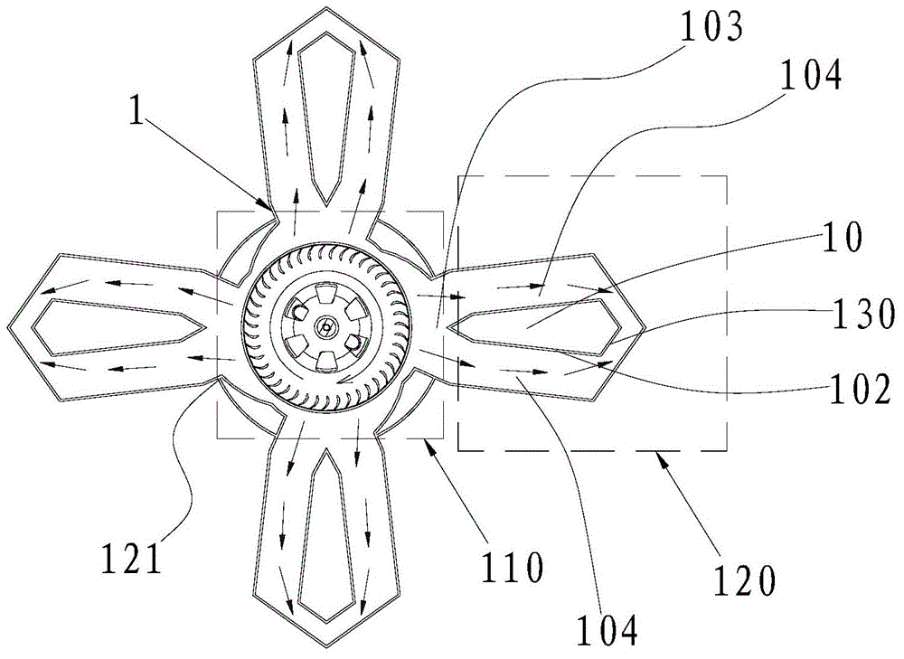
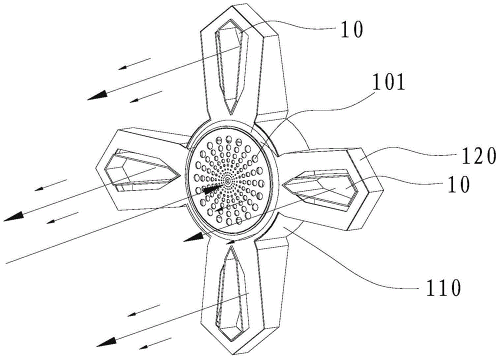
[0060] Such as Figure 1 ~ Figure 4 As shown, the air duct system provided by the embodiment of the present invention can be applied to the fields of fans, air conditioners and other products. The above-mentioned air duct system includes a casing 1 . The casing 1 includes an air inlet portion 110 and an extruding portion 120 having an airflow channel 103, the extruding portion 120 is connected to the side of the air inlet portion 110, the air inlet portion 110 is provided with an air inlet 101, and the extruding portion 120 is provided with a The airflow channel 103 is divided into at least two wind tunnel parts 130 of the flow channel 104 . The wind tunnel part 130 is provided with the wind tunnel 10 passing through the extruding part 120, and the inner wall or periphery of each wind tunnel 10 is provided with an air outlet 102 for blowing out the air flow so that the wind tunnel 10 generates negative pressure. On the side of the wind tunnel part 130, the air outlet 102 com...

Embodiment 2

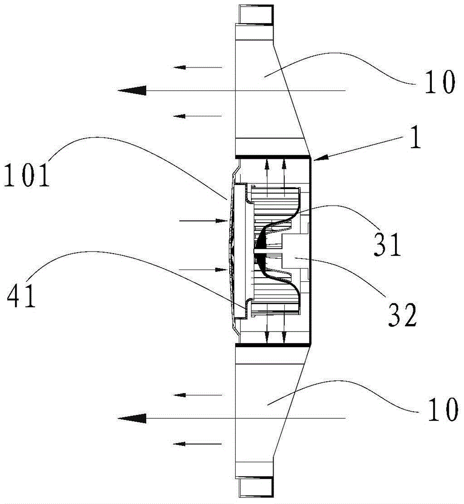
[0071] Unlike the first embodiment where the air inlet is arranged on the front panel 12, in this embodiment, as Figure 5 ~ Figure 8 As shown, the air inlet 101 is opened at the bottom of the bottom case 11 , and the motor 32 is fixedly connected to the front panel 12 . The air flow can enter the air inlet part 110 from the air inlet 101 at the bottom of the housing 1, then flow from the side of the air inlet part 110 to the air flow channel 103 of the extruding part 120, and then blow out from the air outlet 102 forward. The direction of the wind is the same. When the airflow is blown forward from the air outlet 102 along the axial direction of the wind tunnel 10, it will entrain the adjacent airflow and flow forward together, thereby forming a negative pressure at the wind tunnel 10. Under the suction effect of the negative pressure, the wind tunnel 10 The air at the rear is sucked forward and enters from the opening at the rear end of the wind tunnel 10 and flows out from...

Embodiment 3

[0074] Different from Embodiments 1 and 2, in this embodiment, if Figure 9 As shown, the extrusion part 120 is provided with a wind tunnel part 130 and a flow guide 14 for dividing the air flow channel 103 into at least two branch channels 104 . The air guide 14 can be located in the airflow channel 103 to "split" the airflow in the airflow channel 103 into at least two streams to flow into the branch channel 104 to reduce the flow resistance. That is, the splitter can be the inner wall of the wind tunnel 10 , or the flow guide 14 specially arranged. The deflector 14 may be in the shape of a block, or in the shape of a "V" plate or the like. The arrows in the figure indicate the direction of the airflow.

[0075] Specifically, the deflector 14 is arranged at one end of the wind tunnel part 130 close to the air inlet part 110, and the deflector 14 can be in the shape of an acute angle, a right angle, an obtuse angle or an arc, so as to reduce the airflow resistance and make ...


PUM


Abstract

The invention belongs to the technical field of air ducts, and discloses an air duct system, an air supply method of the air duct system and a fan and an air conditioner with the air duct system. An air flow channel is divided into at least two sub channels by air tunnel portions, wind wheels suck air flow in from air inlets, the air flow is made to flow through a heat exchanger and then made to be blown out forwards from air outlets located on the inner side or the periphery of the air tunnels, the air tunnels are front-back through tunnels, air enters an air inlet portion from the air inlets, flows to squeezing portions, then is divided into at least two streams under the effect of the air tunnel portions and then is blown out from the air outlets, air blown out from the air outlets enables the front sides of the air tunnels to form negative air pressure, and air at the rear portions of the air tunnels is sucked forwards and flows out from front end openings of the air tunnels. The air supply effect which is at least multiple times the air inlet capacity of the air inlets is formed through the principles of the aerodynamics, the energy efficiency utilization rate is high, the air supply effect is good, and the energy saving and environment protection effects are good.

Description

technical field [0001] The invention belongs to the technical field of air ducts, and in particular relates to an air duct system and an air supply method thereof, a fan and an air conditioner provided with the air duct system. Background technique [0002] In the air duct structure in the prior art, grid-shaped air inlets and outlets are directly arranged on the casing, and the air outlet efficiency is low. Contents of the invention [0003] The object of the present invention is to overcome the shortcomings of the above-mentioned prior art, and provide an air duct system and its air supply method, a fan and an air conditioner with the air duct system, which have high air outlet efficiency. [0004] The technical solution of the present invention is: an air duct system, including a housing, the housing includes an air inlet part and an extruding part with an airflow channel, the extruding part is connected to the side of the air inlet part, the The air inlet part is prov...

Claims


Application Information

Patent Timeline
Patent Type & Authority Applications(China)
IPC IPC(8): F24F13/02F24F13/10
CPCF24F13/02F24F13/10
Inventor 华龙
Owner GD MIDEA AIR-CONDITIONING EQUIP CO LTD
Why Eureka
Try Eureka