Flatness detection system and method

A detection system and detection method technology, applied in the direction of measuring devices, instruments, etc., can solve the problems of large error in analysis results and many sensors, and achieve the effect of high detection speed and high detection accuracy

Active Publication Date: 2015-03-25
GUANGZHOU COSEN TEST & MEASUREMENT
View PDF4 Cites 14 Cited by
  • Summary
  • Abstract
  • Description
  • Claims
  • Application Information

AI Technical Summary

Problems solved by technology

[0003] Based on this, in order to solve the problem that the above-mentioned traditional flatness detection machine uses many sensors, and the collection points are limited, blind spots, multiple analysis results have large errors, the present invention proposes a flatness detection system and method

Method used


Image

  • Flatness detection system and method
  • Flatness detection system and method
  • Flatness detection system and method

Examples


Embodiment Construction

[0038] Embodiments of the present invention will be described in detail below in conjunction with the accompanying drawings.

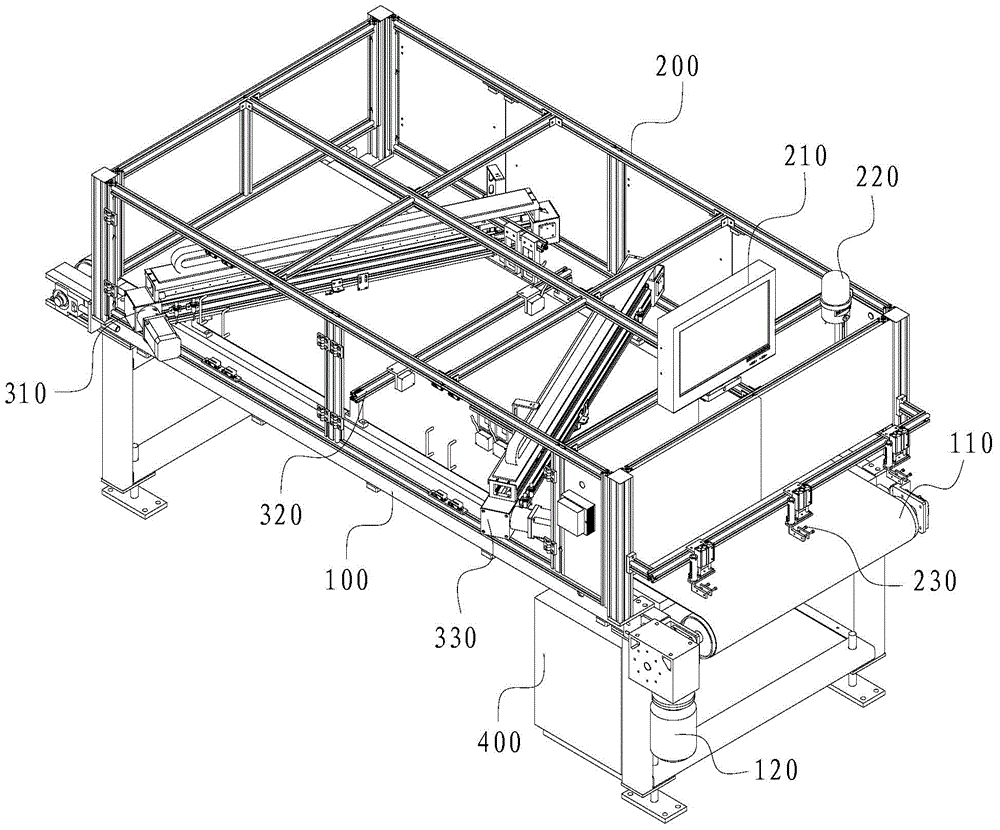
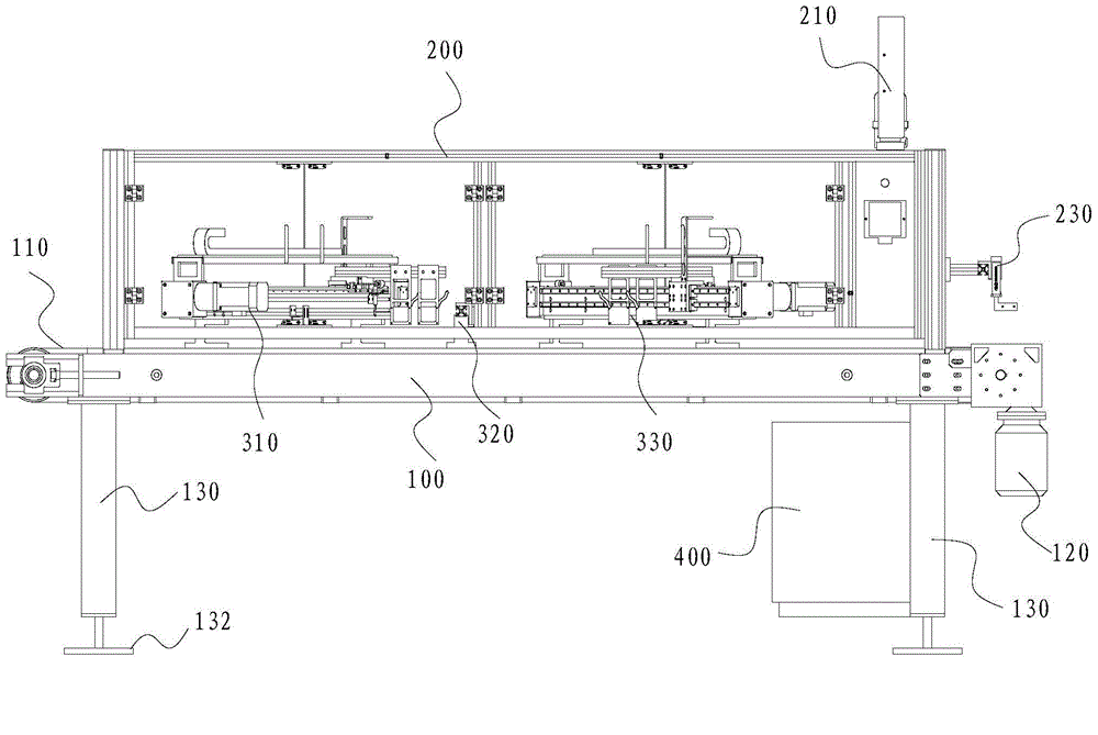
[0039] Such as figure 1As shown, the present invention provides a flatness detection system, including a transmission device 100 provided with a conveyor belt 110, a detection device (not shown in the figure) arranged above the conveyor belt 110, and a protective cover arranged on the detection device 200, and a control device 400 connected with the transmission device 100 and the detection device.

[0040] Such as Figure 1 to Figure 5 As shown, the above-mentioned conveying device 100 includes a conveyor belt 110, and a conveyor belt support 112 arranged on both sides of the conveyor belt 110 for supporting the conveyor belt 110, and also includes a support leg 130 for supporting the conveyor belt support 112, and the support leg 130 A fixed support plate 132 is also arranged below, and the conveying device 100 can be fixed by passing through the f...


PUM


Abstract

The invention discloses a flatness detection system and method. The flatness detection system comprises a conveying device provided with a conveying belt, a detection device arranged above the conveying belt, a protective cover covering the detection device and a control device connected with the conveying device and the detection device. The detection device comprises a first detection mechanism, a second detection mechanism and a third detection mechanism which are arranged in sequence. The first detection mechanism, the second detection mechanism and the third detection mechanism are close to the same side. The number of sensors used in detection is small, all point positions on the four sides and diagonal lines of a rectangular objected to be detected can be acquired, and the number of blind points is small. A high-accuracy displacement sensor is adopted for detection, detection accuracy is high, a servo motor is utilized to drive the sensor to move so that the detection speed can be high and be adjusted.

Description

technical field [0001] The invention relates to the technical field of flatness detection, in particular to a flatness detection system and method. Background technique [0002] The traditional tile flatness testing machine uses a limited number of fixed sensors to collect a limited number of points after being triggered, and the system compares and analyzes the unevenness of the tiles. The traditional flatness testing machine uses multiple sensors, the equipment cost is relatively high, and resources are wasted. The number of points collected by the sensor of the traditional flatness inspection machine is limited, there are many blind spots, and the error of the analysis result is relatively large. Contents of the invention [0003] Based on this, in order to solve the above-mentioned problems that the traditional flatness testing machine uses many sensors, limited collection points, blind spots, multiple analysis results and large error, the present invention proposes a...

Claims


Application Information

Patent Timeline
Patent Type & Authority Applications(China)
IPC IPC(8): G01B21/30
CPCG01B21/30
Inventor 黄小平
Owner GUANGZHOU COSEN TEST & MEASUREMENT
Why Eureka
Try Eureka