
Remote monitoring system

A remote monitoring system and remote host technology, applied in general control systems, control/regulation systems, program control, etc., can solve problems such as stability and reliability that need to be improved

Inactive Publication Date: 2015-03-25
石馀
View PDF0 Cites 3 Cited by
  • Summary
  • Abstract
  • Description
  • Claims
  • Application Information

AI Technical Summary

Problems solved by technology

The stability and reliability of the existing remote monitoring system need to be improved

Method used


Image

  • Remote monitoring system

Examples


Embodiment Construction

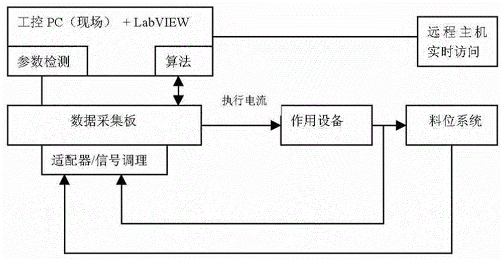
[0011] Such as figure 1 As shown, the present invention comprises PC, data acquisition board, adapter, signal conditioning part, material level system, action equipment, and data acquisition board is connected with PC, adapter, signal conditioning part, action equipment respectively, and material level system is respectively connected with adapter, signal The conditioning part and the functioning equipment are connected.

[0012] The present invention also includes a remote host connected to the PC.

[0013] The PC is an industrial PC.

[0014] The invention mainly realizes the remote monitoring function of LabVIEW. The experimental platform is based on Windows Xp+IIS5.1, using LabVIEW7.1 version. First build a network server, namely Web Server. This can be achieved using PWS or IIS. IIS5.1 that comes with Windows Xp is used here. Open the setting page of IIS5.1, right-click on "Default Web Site", and select "Properties" to enter the setting interface named "Def...


PUM


Abstract

The invention relates to a remote monitoring system and belongs to the monitoring system technical field. The remote monitoring system provided by the invention has the advantages of high stability and high reliability. The remote monitoring system of the invention includes a PC, a data acquisition board, an adapter, a signal conditioning part, a material level system and acting equipment. The remote monitoring system is characterized in that the data acquisition board is connected with the PC, the adapter, the signal conditioning part and the acting equipment respectively; and the material level system is connected with the adapter, the signal conditioning part and the acting equipment respectively.

Description

technical field [0001] The invention belongs to the technical field of monitoring systems, in particular to a remote monitoring system. Background technique [0002] The development of electronic measuring instruments has gone through four generations, namely: analog instruments, discrete component instruments, digital instruments and intelligent instruments. At present, the deep combination of test technology and computer is causing a new revolution in the field of test instruments. A brand-new instrument—virtual instrument came into being. Virtual instrument is an important part of virtual technology. It is a revolutionary technology bred by the rapid development of modern computer software technology, communication technology and measurement technology. Its appearance has brought human testing technology into a new era of development. It is somewhat similar to an intelligent instrument, which is to install the instrument into a computer and rely on general computer har...

Claims


Application Information

Patent Timeline
Patent Type & Authority Applications(China)
IPC IPC(8): G05B19/418
CPCY02P90/02G05B19/0428
Inventor 石馀段邵文徐可
Owner 石馀
Learn More