Pixel driving circuit

A technology of pixel drive circuit and capacitor, which is applied to instruments, static indicators, etc., and can solve problems such as uneven brightness and uneven brightness

Active Publication Date: 2015-03-25
AU OPTRONICS CORP
View PDF6 Cites 12 Cited by
  • Summary
  • Abstract
  • Description
  • Claims
  • Application Information

AI Technical Summary

Problems solved by technology

However, because process variation will cause the threshold voltage (threshold voltage, Vth) of the driving transistor of each pixel in the display to be different, this will cause the light emitting diodes in different pixels to have different driving currents. The brightness of each light-emitting diode is different, which will cause the problem of uneven brightness when the display screen is displayed.

Method used


Image

  • Pixel driving circuit
  • Pixel driving circuit
  • Pixel driving circuit

Examples


Embodiment Construction

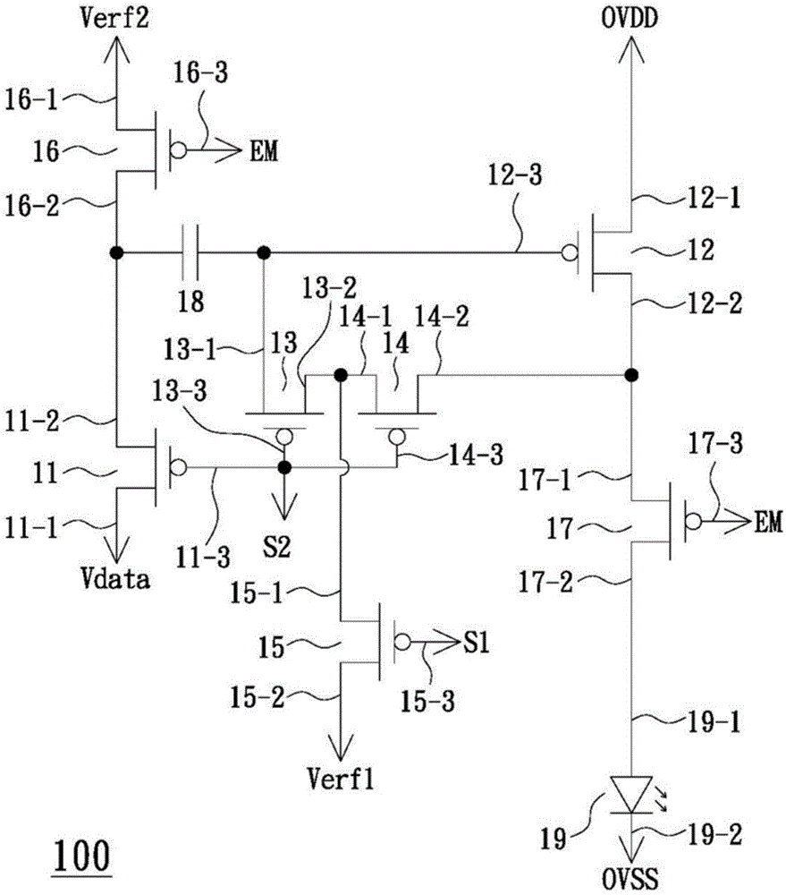
[0024] figure 1 What is shown is a circuit structure diagram of a pixel driving circuit according to an embodiment of the present invention. Such as figure 1 As shown, the pixel driving circuit 100 includes a switch 11 , a switch 12 , a switch 13 , a switch 14 , a switch 15 , a switch 16 , a switch 17 , a capacitor 18 and a light emitting unit 19 . The switch 11 has a first terminal 11-1, a second terminal 11-2 and a control terminal 11-3, and the first terminal 11-1 of the switch 11 is electrically connected to the data voltage Vdata. The switch 12 has a first terminal 12-1, a second terminal 12-2 and a control terminal 12-3, and the first terminal 12-1 of the switch 12 is electrically connected to the operating voltage source OVDD. The switch 13 has a first end 13 - 1 , a second end 13 - 2 and a control end 13 - 3 , the first end 13 - 1 of the switch 13 is electrically connected to the control end 12 - 3 of the switch 12 . The switch 14 has a first end 14-1, a second end ...


PUM


Abstract

A pixel driving circuit comprises a first to seventh switches, capacitance and a light emitting unit, wherein the first and sixth switches are in a serial connection and respectively receive data voltage and a second reference voltage according to a second and third control signals; one end of the capacitance is coupled to a serial connection point between the first and sixth switches, and the other end is coupled to a control end of the second switch; the third and fourth switches are serially connected between one end of the second switch and the control end, and conducted based on the second control signal; the fifth switch is conducted based on a first control signal; one end of the fifth switch is coupled to a serial connection point between the third and fourth switches, and the other end receives the first reference voltage; and the seventh switch is serially connected between the second switch and the light emitting unit, and conducted based on the third control signal.

Description

technical field [0001] The invention relates to a pixel driving circuit, in particular to a pixel driving circuit related to light emitting diodes. Background technique [0002] At present, light emitting diodes have been widely used in various types of displays. The brightness of the light-emitting diode when it emits light is related to the magnitude of its driving current, and the magnitude of its driving current is controlled by the driving transistor. However, because process variation will cause the threshold voltage (threshold voltage, Vth) of the driving transistor of each pixel in the display to be different, this will cause the light emitting diodes in different pixels to have different driving currents. The brightness of each light-emitting diode is different, which in turn causes the problem of uneven brightness when the display screen is displayed. Therefore, a pixel driving circuit capable of compensating for the threshold voltage of a driving transistor of a...

Claims


Application Information

Patent Timeline
Patent Type & Authority Applications(China)
IPC IPC(8): G09G3/32G09G3/3233
CPCG09G2300/0819G09G2310/0216G09G3/3233G09G2320/0233
Inventor 黄冠儒叶佳元刘俊彦
Owner AU OPTRONICS CORP
Why Eureka
Try Eureka