Control method for switching mechanism

A technology of a switch mechanism and a control method, which is applied to the operation/release mechanism of the protection switch, the power device inside the switch, the contact drive mechanism, etc. The effect of promotion and cost reduction

Inactive Publication Date: 2015-03-25
莫文艺
View PDF9 Cites 16 Cited by
  • Summary
  • Abstract
  • Description
  • Claims
  • Application Information

AI Technical Summary

Problems solved by technology

However, in order to ensure the correct operation sequence, its structure and control are more complicated, the reliability is low, and the cost is high.
[0004] The existing switch mechanism control device, such as the Chinese patent application (application number: 201120291912.0) discloses a transmission mechanism of the electric operating mechanism of the miniature circuit breaker. The technical solution adopted is that the electric operating mechanism of the circuit breaker includes There is a casing, a driving motor is installed in the casing, a handle that can rotate around a fixed axis is installed on the casing, a gear is installed at the lower end of the handle and is located in the casing, and a crank arm and a matching arm are installed on the output shaft of the driving motor. The driving gear, the driving gear meshes with the gear, and there is a gap between the crank arm and the supporting device of the driving gear; the electric operating mechanism of the miniature circuit breaker with this structure requires multiple state sampling and complex logic control circuits to realize normal operation. The opening and closing operation is costly, and when the handle is fixed at the closing position for a long time due to external interference, it cannot be opened when remote opening is required in an emergency

Method used


Image

  • Control method for switching mechanism
  • Control method for switching mechanism
  • Control method for switching mechanism

Examples


Embodiment Construction

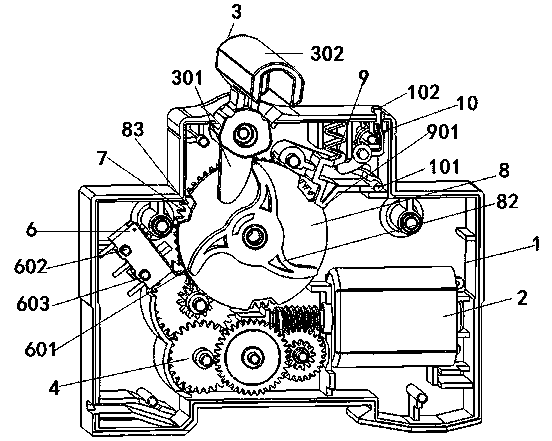
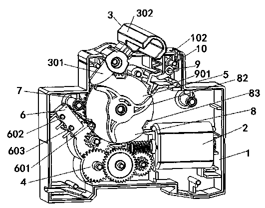
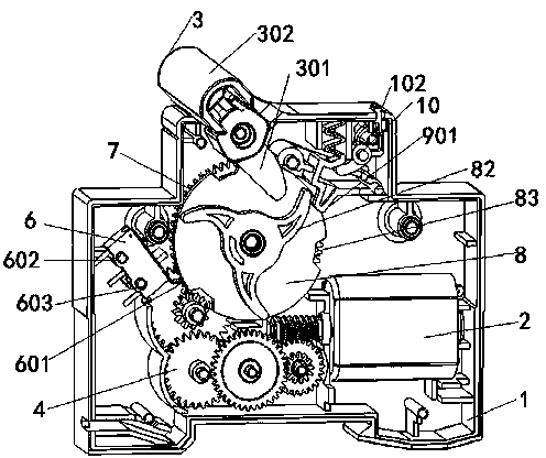
[0036] Such as Figure 1-9 As shown, the control device of the switch mechanism includes a housing 1 provided with several support columns 101, a motor 2, a switch mechanism 3, a reduction gear set 4, a clutch mechanism 5 and a micro switch 6, and the switch mechanism 3 is embedded and fixed in the shell. body 1 on the support column 101 and can rotate around the support column 101; the switch mechanism 3 includes a rotary member 301, a switch sleeve 302, a handle (not shown in the figure), one end of the rotary member 301 is connected with the switch mechanism 3, and the other end Extending into the interior of the housing 1; the switch sleeve 302 is set on the handle; the switch sleeve 302 and the rotary member 301 are integrally formed; the motor 2, the reduction gear set 4, the clutch mechanism 5 and the micro switch 6 are fixed on the housing 1 on the support column 101 inside; one end of the reduction gear set 4 is meshed with the motor 2, and the other end is meshed wit...


PUM


Abstract

The invention relates to a control method for a switching mechanism. According to the control method, a power source, a motor, a closing switch, an opening switch and a micro switch constitute a closed circuit. The control method mainly includes the following steps that the motor is powered on to drive a reduction gear set which is meshed with the motor to rotate; the reduction gear set drives a first gear which is meshed with the reduction gear set to rotate, and a cam mounted on the reduction gear set is made to rotate; an arc-shaped shifting block on the cam shifts a rotating member of the switching mechanism to rotate or revolving member to rotate; the rotating member drives a handle on the switching mechanism to rotate or the revolving member touches the switching mechanism to be disengaged after the revolving member rotates; a lever on the micro switch can rotate around a point of the micro switch, a contact a, a contact b and a contact c of the micro switch are changed, and thus the switching mechanism can be closed or opened automatically. The control mode is quite economical and simple and is beneficial to lowering the cost and promoting the market expansion of products.

Description

technical field [0001] The invention relates to the technical field of electrical switches, in particular to a control method for a switch mechanism. Background technique [0002] Miniature circuit breaker, referred to as MCB, is the most widely used terminal protection device in electrical terminal power distribution devices. It is used for single-phase and three-phase short-circuit, overload, and overvoltage protection below 125A, including single-pole 1P, Two-pole 2P, three-pole 3P, four-pole 4P, etc., for example, miniature circuit breakers are basically used in the terminals of low-voltage power distribution. At present, with the continuous improvement of various indicators of miniature circuit breakers, its applications are becoming more and more extensive, but the requirements for its performance and automatic operation are also getting higher and higher. [0003] The electric operating mechanism of the circuit breaker is an accessory used for remote electric opening...

Claims


Application Information

Patent Timeline
Patent Type & Authority Applications(China)
IPC IPC(8): H01H71/10H01H71/70
CPCH01H3/26H01H3/40H01H3/42H01H71/10H01H71/70
Inventor 不公告发明人
Owner 莫文艺
Why Eureka
Try Eureka