
An electrostatic chuck and its gas supply method

An electrostatic chuck and helium technology, which is applied in the manufacture of electrical components, circuits, semiconductor/solid-state devices, etc., can solve problems such as changes in reaction conditions, leakage, inconsistent effects between the center and edge areas of the substrate 30, and achieve good temperature distribution. , to ensure the effect of cooling effect

Active Publication Date: 2017-09-05
ADVANCED MICRO FAB EQUIP INC CHINA
View PDF5 Cites 0 Cited by
  • Summary
  • Abstract
  • Description
  • Claims
  • Application Information

AI Technical Summary

Problems solved by technology

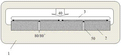
However, the helium 60 leaks at the edge of the substrate 30 and mixes with the process gas 40 (reference number 70 is a gas mixing area), so that the reaction conditions at the edge of the substrate 30 are changed, resulting in the substrate 30 Inconsistent effects after the center and edge areas are made

Method used


Image

  • An electrostatic chuck and its gas supply method
  • An electrostatic chuck and its gas supply method
  • An electrostatic chuck and its gas supply method

Examples


Embodiment 1

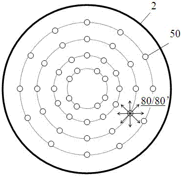
[0027] Such as figure 2 As shown, in the first embodiment of the present invention, the first process gas 40 is introduced into the vacuum processing chamber 1 to etch or otherwise process the surface of the substrate 3, and the bottom of the vacuum processing chamber 1 is provided with static electricity. The chuck 2 fixes and supports the substrate 3 placed on the electrostatic chuck 2 . A number of gas passages 50 are opened in the electrostatic chuck 2 to introduce cooling gas from the bottom of the electrostatic chuck 2 to its top surface. Afterwards, the cooling gas is blown through the gap between the back surface of the substrate 3 and the top surface of the electrostatic chuck 2 , so as to flow through the entire back surface of the substrate 3 for heat transfer, thereby cooling the substrate 3 .

[0028] Wherein, the diameter of the electrostatic chuck 2 in this embodiment is equal to or greater than the diameter of the substrate 3 . At the same time, the gas comp...

Embodiment 2

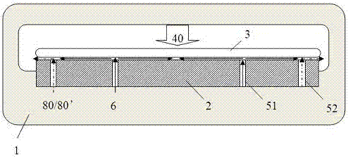
[0034] Such as Figure 4 As shown, in the second embodiment of the present invention, the electrostatic chuck 2 is located at the bottom of the vacuum processing chamber 1, and is used to fix and support the substrate 3 placed on it, and the first process gas 40 is introduced from above to the substrate. 3 The surface is etched or otherwise treated. The diameter of the electrostatic chuck 2 is equal to or larger than that of the substrate 3 . Moreover, two groups of gas channels, the first channel 51 and the second channel 52 , are provided in the electrostatic chuck 2 , which are respectively used to transport gas to the gap between the back surface of the substrate 3 and the top surface of the electrostatic chuck 2 .

[0035] Wherein, the first channel 51 is located in the central area 91 of the electrostatic chuck 2, and is used to transport cooling gas, preferably helium 60; The second process gas 80 or 80' with the same or very close composition ratio, which separates t...


PUM


Abstract

The invention relates to an electro-static sucker and a gas supply method of the electro-static sucker. The diameter of the electro-static sucker located at the bottom in a vacuum processing room is equal to or larger than the diameter of a substrate fixedly supported by the electro-static sucker. Second process gas is conveyed to the edge position of the back face of the substrate through gas channels located on the edge of the electro-static sucker, and helium or second process gas is conveyed to the center position of the surface of the substrate through gas channels located in the center of the electro-static sucker to conduct heat transmission cooling. Due to the fact that the composition of the second process gas is identical or quite close to the composition of first process gas conveyed to the surface of the substrate to conduct reaction processing, it can be ensured that reaction conditions needed when the edge of the substrate is processed cannot not be changed by the gas obtained after the second process gas and the first process gas are mixed. Thus, the gas supply method can be applied to the electro-static sucker with larger size so that the better temperature distribution effect can be obtained on the substrate.

Description

technical field [0001] The invention relates to the field of semiconductor manufacturing, in particular to an electrostatic chuck and a gas supply method thereof. Background technique [0002] Such as figure 1 Shown is a schematic structural view of a conventional vacuum processing chamber 10 . The process gas 40 enters the vacuum processing chamber 10 from the top to perform etching, film deposition or other processing on the surface of the substrate 30 . The bottom of the vacuum processing chamber 10 is provided with an electrostatic chuck 20 for fixing and supporting the substrate 30 placed on the electrostatic chuck 20 during processing. As a cooling gas, helium 60 first passes through several gas channels 50 opened in the electrostatic chuck 20, passes through the electrostatic chuck 20 from below to reach its top surface, and then flows through the gap between the back surface of the substrate 30 and the top surface of the electrostatic chuck 20. The heat is transfe...

Claims


Application Information

Patent Timeline
Patent Type & Authority Patents(China)
IPC IPC(8): H01L21/67H01L21/683
CPCH01L21/67H01L21/6831
Inventor 万磊倪图强
Owner ADVANCED MICRO FAB EQUIP INC CHINA
Learn More