

Electrical cabinet wire duct
A technology for power cabinets and trunking, applied in the direction of electrical components, etc., can solve the problems of wasting time, cable ties passing through, increasing the use of cable ties, etc.
- Summary
- Abstract
- Description
- Claims
- Application Information
AI Technical Summary
Problems solved by technology
Method used
Image

Examples
Embodiment Construction
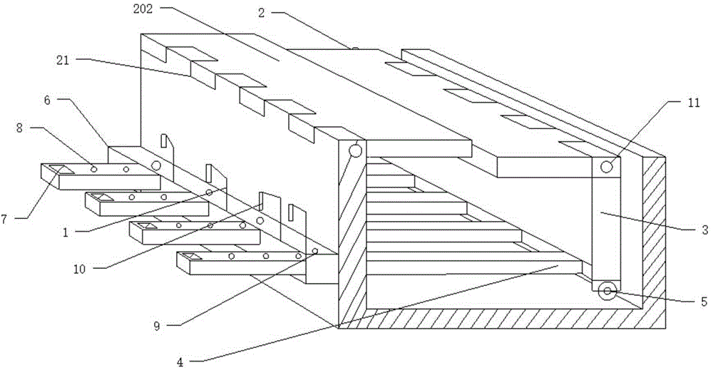
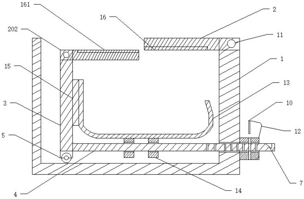
[0031] Such as figure 1 As shown, a power cabinet trunking includes a "U"-shaped trunking body 1, and a sliding pressing plate 3 is arranged inside the trunking body 1, as figure 2 As shown, the bottoms of both sides of the pressing plate 3 are provided with pulleys 5 . During use, the pulleys 5 on both sides of the pressing plate 3 can allow the pressing plate 3 to slide smoothly in the trunking body 1, which can further facilitate pulling the pressing plate 3, and can avoid rigid friction between the pressing plate 3 and the trunking body 1.
[0032] A plurality of pull rods 4 are connected to the bottom of the pressing plate 3, and a locking block 6 is connected to one side of the trunking body 1. The locking block 6 is provided with a passage corresponding to the pull rod 4 and allowing the pull rod 4 to pass through. hole, the through hole runs through the wire slot body 1, the pull rod 4 slides in the through hole of the wire slot body 1 and the locking block 6, where...
PUM
 Abstract
Description
Claims
Application Information