Transfer device

A technology for transferring devices and components, which is applied to lifting devices, storage devices, loading/unloading, etc., can solve the problems of short side arms and restrict the movable range of the side arms, and achieve the effect of expanding the movable range.

Active Publication Date: 2016-06-15
MURATA MASCH LTD
View PDF5 Cites 0 Cited by
  • Summary
  • Abstract
  • Description
  • Claims
  • Application Information

AI Technical Summary

Problems solved by technology

For example, in the transfer device described in Patent Document 1, since a conveyor is arranged between a pair of side arms, the distance between the side arms cannot be made shorter than the width of the conveyor, and the movable range of the side arms is restricted.

Method used


Image

  • Transfer device
  • Transfer device
  • Transfer device

Examples


Embodiment Construction

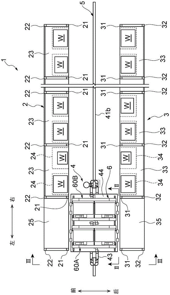
[0025] One embodiment of an automatic warehouse using the transfer device of the present invention will be described below with reference to the drawings. In addition, in this embodiment, if figure 1 As shown, the moving direction of the transfer device 6 figure 1 In the left-right direction in , the right side is called "right" and the left side is called "left" to describe the direction. Such as figure 1 As shown, when going to the right side from the transfer device 6, the direction will be described by referring to the left side as "front" and the right side as "rear". That is, the left-right direction and the front-rear direction are perpendicular to each other.

[0026] (The overall structure of the automatic warehouse)

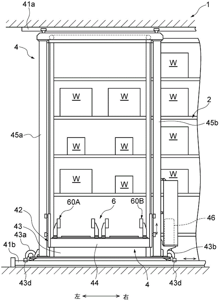
[0027] Such as figure 1 As shown, the automatic warehouse 1 includes a front frame 2, a rear frame 3, and a stacking crane 4 that travels between them.

[0028] (bracket)

[0029] The front frame 2 and the rear frame 3 are respectively disposed a...


PUM


Abstract

The transfer device (6) includes a lifting platform (44), a pair of side arms (100A, 100B) placed on the lifting platform (44) and capable of telescopically extending to both sides of the cargo (W), and a pair of side arms (100A, 100B) mounted on the lifting platform (44). The lower conveyor (200) on the table (44). At least one side arm (100A) among a pair of side arms (100A, 100B) is movable in the left-right direction orthogonal to the expansion and contraction direction of the side arm (100A). One side arm (100A) is provided with a base member (130A) movable in the left-right direction. A front-side guide leg member (132A) and a rear-side guide leg member (134A) are respectively provided below both ends of one base member (130A) in the telescopic direction. The lower conveyor (200) is provided below the base body member (131A) and between the front-side guide leg member (132A) and the rear-side guide leg member (134A).

Description

technical field [0001] The present invention relates to a transfer device for transferring objects to be conveyed. Background technique [0002] Conventionally, there is a transfer device provided with a side arm. The transfer device extends a pair of side arms to both sides of the object placed on the shelf, etc., hooks the two sides of the object with a pair of side arms, or clamps the object with a pair of side arms. The object to be carried is transferred to the transfer device by contracting the side arm. There is known a transfer device provided with a conveyor for smooth delivery of objects to be conveyed between a rack and the transfer device (see, for example, Patent Document 1). [0003] Prior art literature [0004] patent documents [0005] Patent Document 1: Japanese Patent Laid-Open No. 2012-71931 [0006] Summary of the invention [0007] The problem to be solved by the invention [0008] Among them, the transfer device sometimes changes the distance be...

Claims


Application Information

Patent Timeline
Patent Type & Authority Patents(China)
IPC IPC(8): B65G1/04
CPCB65G1/0435B65G2201/025B65G1/0407B66F9/141B65G65/08
Inventor 山田文惠
Owner MURATA MASCH LTD
Why Eureka
Try Eureka