Feeding frame for cutting machine

A cutting machine and material rack technology, which is applied in metal processing machinery parts, large fixed members, metal processing, etc., can solve the problems of few research directions, inconvenient operation, and large plate volume.

Inactive Publication Date: 2015-04-01
WUHU BEST NEW ENERGY DEV
View PDF7 Cites 0 Cited by
  • Summary
  • Abstract
  • Description
  • Claims
  • Application Information

AI Technical Summary

Problems solved by technology

[0002] At present, mechanical processing is becoming more and more common, and mechanical equipment is also changing with each passing day, with complex shapes, so equipment personnel are paying more and more attention to complex and new equipment. At the same time, for some equipment that can be easily operated with simple equipment...

Method used


Image

  • Feeding frame for cutting machine

Examples


Embodiment Construction

[0021] Specific embodiments of the present invention will be described in detail below in conjunction with the accompanying drawings. It should be understood that the specific embodiments described here are only used to illustrate and explain the present invention, and are not intended to limit the present invention.

[0022] In the present invention, in the case of no contrary description, the used orientation words such as "up, down, left and right" usually refer to the up, down, left and right shown in the accompanying drawings; "inside and outside" Refers to the inside and outside of the outline of each part itself.

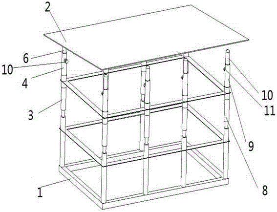
[0023] The invention provides a feeding rack for a cutting machine, such as figure 1 As shown, the loading frame includes an underframe 1, a plurality of first telescopic adjustment rods and a plurality of second telescopic adjustment rods, and the first telescopic adjustment rods and the second telescopic adjustment rods are vertically arranged , and respe...


PUM


Abstract

The invention discloses a feeding frame for a cutting machine. The feeding frame comprises an under-frame, a plurality of first telescopic adjustment rods and a plurality of second telescopic adjustment rods, the first telescopic adjustment rods and second telescopic adjustment rods are vertically arranged at two sides of the under-frame, and the telescopic length of each first telescopic adjustment rod is larger than or smaller than the telescopic length of each second telescopic adjustment rod; each first telescopic adjustment rod comprises a first connecting rod and a first spring rod, the first connecting rod is firmly connected with the under-frame, one end of the first spring rod is connected with the first connecting rod through a first spring, and the other end is provided with a first pulley; each second telescopic adjustment rod comprises a second connecting rod and a second spring rod, the second connecting rod is firmly connected with the under-frame, and one end of the second spring rod is connected with the second connecting rod through a second spring while the other end is provided with a second pulley. The feeding frame is convenient for a piece to be processed to enter the cutting machine and capable of improving the cutting speed.

Description

technical field [0001] The invention relates to the field of mechanical processing, in particular to a feeding rack for a cutting machine. Background technique [0002] At present, mechanical processing is becoming more and more common, and mechanical equipment is also changing with each passing day, with complex shapes, so equipment personnel are paying more and more attention to complex and new equipment. At the same time, for some equipment that can be easily operated with simple equipment There are fewer and fewer research directions for steps. For example, there is no device to support the plate when the cutting machine is working. Generally, the plate is put into the cutting machine for cutting by manual operation. Because of the large volume of the plate, it is inconvenient to operate and the speed is relatively slow. Contents of the invention [0003] The object of the present invention is to provide a material loading rack for cutting the boards by the cutting ma...

Claims


Application Information

Patent Timeline
IPC IPC(8): B23Q1/72B23Q7/00
CPCB23Q1/76B23Q7/00
Inventor 刘艺超
Owner WUHU BEST NEW ENERGY DEV
Why Eureka
Try Eureka